


Service Reference Manual SEQUENCE OF OPERATIONS
2-5
SRM-HW/HWC 2/99
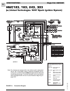
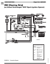
Simplified Sequence - HWC123,183, 243, 303
Refer to Figure 2-1
• 208/230V power is supplied to the junction box on
top of the unit
• 24V power is supplied from the unit transformer to
the thermostat
CALL FOR HEAT
1. The thermostat closes the R-W circuit, sending a
24-volt signal to the unit.
2. The 24-volt signal energizes the combustion blower,
causing the pressure switch to close.
3. The combustion blower runs for 30 seconds as a
pre-purge to trial for ignition.
4. The ignition control energizes the spark ignition and
opens the gas valve, causing the burners to light.
When the gas valve energizes, a 30-second circu-
lating air blower “on” delay begins.
5. Flame sense is sent to the ignition control through
the flame sensor and flame sense wire.
6. After the 30-second delay, the circulating air blower
energizes and runs until the heat call is satisfied.
7. When the heat call is satisfied, the gas valve de-
energizes. This shuts down the burners.
8. A 5-second combustion blower post-purge delay
and a 120-second circulating air blower “off” delay
start.
9. After the delay times elapse, the combustion blower
and the circulating air blower stop.
FLAME SENSE
1. After the burners have been lit, the ignition control
starts a 10-second trial for ignition delay.
2. If after 10 seconds a flame has not been sensed by
the ignition control, the ignition control de-energizes
the gas valve and the spark ignitor.
3. The unit initiates three trials for ignition (flame
sense) before system lockout.
4. System lockout lasts 60 minutes or until power is
reset to unit (whichever comes first).
CALL FOR COOLING
1. The thermostat energizes the R, Y and G circuit,
sending a 24-volt signal to the cooling contactor and
the ignition control to start the cooling sequence.
2. The contactor closes immediately, causing the
compressor and the condenser fan to run.
3. The 24-volt Y signal starts a 5-second circulating air
blower “on” delay.
4. After 5 seconds, the circulating air blower starts and
runs until the R, Y and G circuit is interrupted by the
thermostat.
5. When the R, Y and G circuit is interrupted, the
cooling contactor immediately de-energizes. This
causes the compressor and the condenser fan to
stop.
6. The ignition control starts a 90-second circulating
air blower “off” delay.
7. After 90 seconds, the circulating air blower stops.
FAN ON
1. The thermostat energizes the R-G circuit, causing
the circulating air blower to energize in cooling
speed.
2. The circulating air blower remains running in cooling
speed until the thermostat is switched to the “AUTO”
position.
Detailed Sequence follows