


Service Reference Manual SEQUENCE OF OPERATIONS
2-25
SRM-HW/HWC 2/99
9. When W de-energizes, the gas valve immediately
shuts down and the induced draft blower also
stops after several seconds.
10. The blower control board starts a countdown to
blower “off”. Approximately 90 seconds later, the
circulating air blower shuts down.
LIMIT OPENS
If the limit switch opens for any reason during a call for
heat, the following happens:
1. If the limit switch senses that the temperature in
the unit is too high, the circuit between terminals C
and NC on the limit switch opens. This closes the
circuit between terminals C and NO on the limit
switch, interrupting the 24-volt signal to the pres-
sure switch and the rollout switch and causing
terminal P.SW on the ignition control to de-
energize. The gas valve immediately closes, as
there is no longer a 24-volt signal at terminal V1 on
the ignition control. With 24 volts still going to the
blower control board and terminal TH on the
ignition control, the circulating air blower and
induced draft blower continue to run.
2. The circulating air blower and the induced draft
blower continue to run as long as there is a call for
heat from the thermostat or the limit switch
remains open.
3. When the limit switch senses that the temperature
in the unit is low enough, the circuit between C and
NO opens and the circuit between C and NC
closes.
4. With the limit switch closed, the unit again makes
a trial for ignition and returns to normal operation.
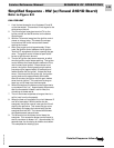
PRESSURE SWITCH OPENS (BLOCKED FLUE)
1. If blockage of the flue occurs, the negative pressure
in the induced draft blower is reduced. At the set
point of the pressure switch, the contacts open.
This interrupts the 24-volt signal coming from
terminal NC on the limit switch. Terminal P.SW on
the ignition control de-energizes, as does terminal
V1. With loss of the 24-volt signal to the gas valve,
the valve closes immediately.
2. Terminals TH on the ignition control and W on the
blower control board remain energized. The
induced draft blower and the circulating air
blower continue to run.
3. When the pressure switch senses that there is
enough negative pressure within the flue, it will
again close the circuit between the limit switch and
terminal P.SW on the ignition control.
4. The unit makes a trial for ignition and returns to
normal operation.
Note: If the P.SW and TH terminals energize at the
same time, the ignition control will not respond.
A pressure switch being stuck closed is an
example of what would cause this to happen.
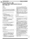
ROLLOUT SWITCH ACTIVATED
1. If the conditions in the burner compartment cause
the rollout switch to trip, the contacts on the switch
open. This interrupts the 24-volt signal going to
terminal P.SW on the ignition control, causing
terminal V1 on the ignition control to de-energize.
This interrupts the 24-volt signal to the gas valve
and immediately closes it. Since terminal TH on the
ignition control and W on the blower control
board remain energized, the induced draft
blower and the circulating air blower continue to
run.
2. The 24-volt signal to the ignition control can only
be restored if the rollout switch is manually reset.
3. Once the cause of the rollout switch being tripped
has been determined, the switch can be reset.
4. With the rollout switch reset, terminal P.SW on the
ignition control again energizes. The ignition
control makes a trial for ignition and operation
returns to normal.