


6-12
INSTALLATION Magic-Pak: HW/HWC
SRM-HW/HWC 8/99
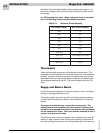
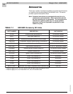
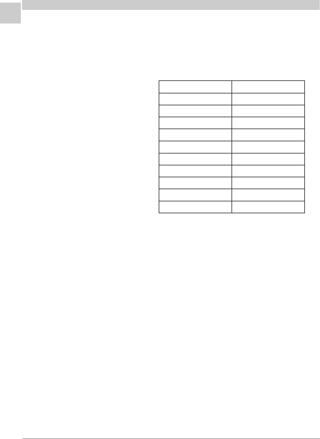
TABLE 6-3 Minimum Circuit Ampacity
See Table 6-3 and the Specifications section beginning on page 1-1 for
correct wire ampacity for the cooling chassis required, and size the wire
accordingly.
For HW (heating only units): When sizing wire, keep in mind that
an air conditioning chassis may be added in the future.
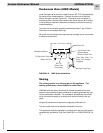
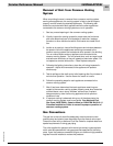
Thermostat
Install the thermostat according to the directions furnished with it. The
thermostat must be located on an inside wall where it will not be affected
by drafts, sunlight or any other heat producing appliances. Connect the
thermostat wires to the low voltage leads on top of the unit following the
wiring diagram attached to the unit. The heat anticipator setting is 0.50
Amp.
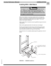
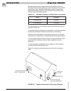
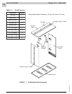
Supply and Return Ducts
Provide ducts sized sufficiently to handle the larger of the air volumes for
heating or cooling provided by the unit.
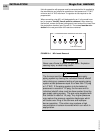
Connect the supply duct to the top of the unit using canvas connections
or other flexible connections to prevent noise transmission into the duct
system.
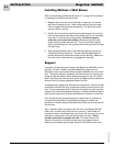
The supply duct should have a removable access panel. The
opening should be accessible when the furnace is installed and
should be large enough and located such that the heat exchanger
can be inspected for leaks. The cover must be attached in such a
manner as to prevent air leaks.
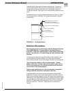
To connect the return duct to the system, use a straight piece of duct 22"
wide by 6" deep. Insert the duct into the return opening in the bottom of
the unit and flange the duct over the existing flanges around the opening
ledoMsissahC.glCyticapmAtiucriC.niM
A8161
A4242
A0372
1813.31
14212
1036.32
321,2213.8
381,281llorcS4.51/yratoR6.31
342,2426.81
303,2034.22