


5-12
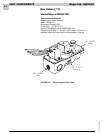
UNIT COMPONENTS Magic-Pak: HW/HWC
SRM-HW/HWC 2/99
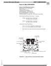
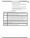
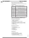
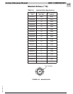
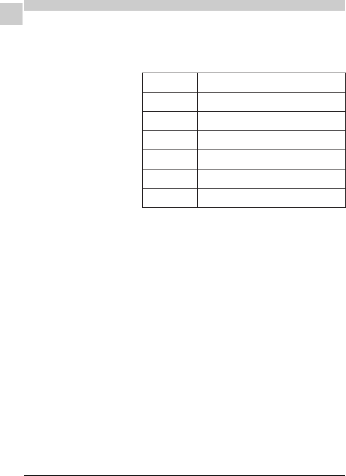
TABLE 5-2 UTech Model 1097 Diagnostic Flash Code
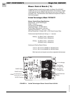
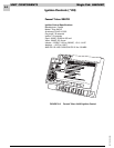
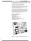
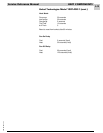
United Technologies Model 1097-400-1 (cont.)
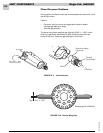
Quick Connect Terminal Descriptions
1 24VAC HOT - from Transformer
2 GROUND = 24VAC Return
4 CMB BLWR = Combustion Blower (Line Voltage)
5 L1 = Line Voltage
9 ACB COOL = Air Circulating Blower Cool Speed (Line Voltage)
10 ACB HEAT = Air Circulating Blower Heat Speed (Line Voltage)
11 UNUSED (Park)
12 FLAME = Flame Probe
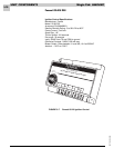
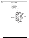
Molex/Amp Plug-in Description
1 Roll-out Switch Return
2 Hi Limit Return/Pressure Switch Out
3 Gas Valve Common
4 Gas Valve Out
5 Pressure Switch Return
6 Roll-out Switch Out
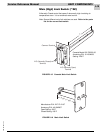
Thermostat Input
R 24VAC to Thermostat (RED)
G Manual Fan Input from Thermostat (GREEN)
W Heat Demand Input from Thermostat (WHITE)
C Common Ground to Thermostat
Y Cool Demand Input from Thermostat (YELLOW)
Diagnostics (United Technologies 1097-400-1)
The following blower/ignition control board LED codes indicate normal or
abnormal operations:
HSALFWOLStaeHrofllaCoN,noitarepOlamroN
HSALFTSAFtaeHrofllaC,noitarepOlamroN
HSALF2emalFniatsuSrotceteDotdeliaF-tuokcoLmetsyS
HSALF3desolCronepOhctiwSerusserP
HSALF4nepOhctiwStuolloRrotimiLhgiH
HSALF5dezigrenEtoNevlaVsaGdnadesneSemalF
YDAETS)kcehc-fleS;eruliaFrellortnoc-orciM(eruliaFlanretnI