


Service Reference Manual SEQUENCE OF OPERATIONS
2-35
SRM-HW/HWC 2/99
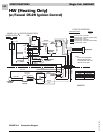
8. When the call for heat is satisfied, the circuit be-
tween R and W is interrupted, de-energizing W.
9. With W de-energized, the gas valve closes immedi-
ately and the induced draft blower stops several
seconds later.
10. The blower control board starts a 90-second
blower “off” delay. Approximately 90 seconds later,
the blower stops.
FLAME SENSE
1. During a call for heat, the spark terminal is ener-
gized and the gas valve is opened to light the
burners.
2. The ignition control energizes the spark terminal
and the gas valve for approximately six seconds. If
a flame is not sensed in this time period, the igni-
tion control de-energizes the spark terminal and
the gas valve. This causes the gas valve to close
and the burners to shut off.
3. Since the 24-volt signal has been sent to the
blower control board, the circulating air blower
times on in approximately 60 seconds.
4. The induced draft blower continues to run for
approximately 30 seconds, then another trial for
ignition begins.
5. The ignition control runs three trials for ignition. If
a flame is not sensed during these three trials, the
ignition control will lockout.
6. The circulating air blower continues to run until
the R-W circuit at the thermostat is interrupted.
7. The ignition control remains in lockout until 24-volt
power to the ignition control is reset.
LIMIT OPENS
If the limit switch opens for any reason during a call for
heat, the following happens:
1. If the limit switch senses that the temperature in
the unit is too high, the contacts between terminals
C and NC on the limit switch open and the con-
tacts between C and NO close. This interrupts the
24-volt signal to the pressure switch and also de-
energizes terminal P.SW on the ignition control.
The gas valve closes immediately, as the 24-volt
signal to terminal P.SW is no longer present. The
induced draft blower and the circulating air
blower continue to run. Power to blower control
board terminal W is maintained. The blower
continues to run until the limit switch closes or the
heat call at the thermostat is satisfied.
2. When the limit switch senses that the tempera-
tures in the unit are normal, the contacts between
terminals C and NO open, the contacts between
terminals C and NC close and the operation of the
unit returns to normal.
PRESSURE SWITCH OPENS (BLOCKED FLUE)
1. If blockage of the flue occurs, negative pressure in
the induced draft blower is reduced. At the set
point of the pressure switch, the contacts open.
This interrupts the 24-volt signal to terminal P.SW
on the ignition control. The gas valve closes
immediately, as a relay in the ignition control
opens and interrupts the signal to terminal V2 of the
ignition control.
2. Terminal W on the blower control board stays
energized and the circulating air blower contin-
ues to run. If negative pressure is restored, the
pressure switch closes and sends a 24-volt signal
to the P.SW terminal on the ignition control. The
ignition control makes a trial for ignition again and
the operation returns to normal.
ROLLOUT SWITCH ACTIVATED
1. If conditions in the burner compartment cause the
rollout switch to trip, the contacts on the switch
open, interrupting the 24-volt signal going to termi-
nal P.SW on the ignition control. This causes the
ignition control to de-energize terminal V1,
interrupting the 24-volt signal to the gas valve and
immediately closing it.
2. The reason the rollout switch was tripped must be
determined before any corrective action is taken.
3. The signal to terminal P.SW can only be restored if
the rollout switch is reset, which can only be done
manually. The W terminal on the blower control
board remains energized and the circulating air
blower continues to operate. Once the rollout
switch is reset, the operation of the unit returns to
normal.