


Service Reference Manual SEQUENCE OF OPERATIONS
2-11
SRM-HW/HWC 2/99
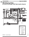
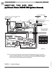
Simplified Sequence - HW (w/UTEC 1097 Board)
Refer to Figure 2-2
CALL FOR HEAT
1. The indoor thermostat energizes the R-W circuit,
sending a 24-volt signal to the ignition control.
2. The 24-volt signal causes the induced draft blower
to start, which closes the pressure switch.
3. Once the pressure switch closes, a 30-second
induced draft blower pre-purge starts.
4. After the 30-second induced draft blower pre-purge,
the gas valve opens and the burners ignite. This
starts a 30-second circulating air blower “on” delay.
5. The unit continues to operate in the heat mode until
the indoor thermostat setting is reached. At that
time, the R-W circuit is interrupted.
6. The 24-volt signal to the ignition control is inter-
rupted, causing the gas valve to close and the
burners to shut down.
7. A 5-second post-purge starts and following that the
induced draft blower stops.
8. A 120-second circulating air blower “off” delay
starts. After the elapsed time, the circulating air
blower stops.
FAN ON
1. When the thermostat is switched to the “FAN ON”
position, a 24-volt signal is sent to the ignition
control.
2. The ignition control immediately energizes the
cooling speed of the circulating air blower.
3. The circulating air blower runs in the cooling speed
until the thermostat fan switch is moved back to the
“AUTO” position. At this time, the circulating air
blower stops.
During the call for “FAN ON”, the circulating air blower
heat speed will not be energized by the ignition control
unless the limit switch circuit is interrupted.
Detailed Sequence follows