


SPECIFICATIONS Magic-Pak: HW/HWC
2-24
SRM-HW/HWC 2/99
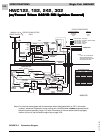
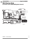
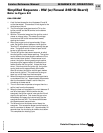
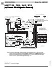
Detailed Sequence - HW
(w/Fenwal Triton 2461D Ignition Control)
Refer to Figure 2-4
POWER
Line Voltage
When the service disconnect switch is closed, power is
sent to the unit (unit in standby, no signal from thermo-
stat). Power (208 - 230 volts A/C) is supplied to the two
black wires located in the junction block on top of the
unit.
Line voltage will be present at the following locations:
First black wire
1. L-1 on the ignition control
2. Terminal on the transformer marked 208V or
240V (whichever is being used)
3. Common terminal on the blower capacitor
Second black wire
1. Supplies power to the one side of the induced
draft blower
2. Common terminal on the transformer
3. L terminal on the blower control board
Low Voltage (24 VAC)
With the unit at rest (no call from the thermostat), 24
volts A/C will be found at the following points:
1. Red wire exiting the top of the unit
2. Terminal marked NO on the limit switch
2. Terminal marked 24VAC on the ignition control
3. Terminal R on the blower control board
CALL FOR HEAT
Line Voltage
The thermostat closes the circuit between R and W.
The following is the sequence of operation for the line
voltage side of the unit:
1. Terminal TH on the ignition control energizes,
causing a relay in the ignition control to close.
This sends line voltage to terminal IND on the
ignition control, causing the induced draft
blower to start.
2. When W is energized, a 24-volt signal is also sent
to the W terminal on the blower control board.
Approximately 60 seconds after W terminal ener-
gizes, the timer on the blower control board
closes the heat speed relay on the board. This
sends line voltage to the H terminal on the blower
control board, which starts the circulating air
blower.
3. The induced draft blower and the circulating air
blower continue to operate as long as W is ener-
gized.
4. When W de-energizes, a relay in the ignition
control opens. Terminal IND de-energizes and the
induced draft blower shuts down. Approximately
90 seconds later, the circulating air blower also
shuts down.
Low Voltage
The following is the sequence of operation for the low
voltage side of the unit on a heat call:
1. A call for heat closes the circuit in the thermostat
between R and W, sending a 24-volt signal to the
white wire on the unit.
2. The white wire goes to the C terminal on the limit
switch.
3. The 24-volt signal is sent from the C terminal
(brown wire) on the limit switch to terminal TH on
the ignition control. This causes the ignition
control to close the line voltage relay, starting the
induced draft blower. When the induced draft
blower comes up to speed and creates enough
negative pressure, the pressure switch closes.
4. With the pressure switch closed, the 24-volt signal
goes to the rollout switch located over the burners.
5. The 24-volt signal from the rollout switch goes to
the terminal marked P.SW on the ignition control,
causing the ignition control to make a trial for
ignition (sparking). Terminal V1 on the ignition
control also energizes at this time, causing the gas
valve to open.
6. At the same time that the C terminal on the limit
switch energizes, a 24-volt signal is also sent to the
W terminal on the blower control board. This
starts the timer on the blower control board.
Approximately 30 seconds after the main burners
ignite, the blower control board closes a relay;
this sends line voltage to the circulating air
blower, starting the blower.
7. As long as W (white wire) is energized, the unit
continues to operate.
8. When the heat call is satisfied, the circuit between R
and W is interrupted.