


3-2
UNIT TEAR DOWN Magic-Pak: HW/HWC
SRM-HW/HWC 8/99
UNIT TEAR DOWN
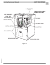
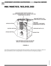
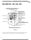
HWC units are comprised of two major sections.
The heating section is located in the top half of the unit. It contains the
heat exchanger and the majority of the components associated with the
heating function: controls, burners, switches, etc.... The total heating
section is not removable as a complete unit. The heat exchanger may be
removed separately for service (see below).
The cooling section is located in the lower half of the unit. It contains
the compressor, coils and motors that make up the refrigeration system.
The cooling section is referred to as the “chassis” of the cooling system.
The chassis is removable as a complete unit. Removal of the chassis
allows service to be performed away from the job site, thus allowing a
spare chassis to be installed to reduce downtime at a residence. Bench
tests may be performed on chassis. See the Performance Test section
beginning on page 9-11 for chassis performance data of both bench
tested and installed units.
Heating Section
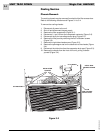
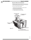
Heat Exchanger Removal:
The heat exchanger may be removed from the unit through the front side.
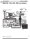
Refer to the following directions and Figure 3-1.
To remove the heat exchanger:
1. Disconnect all power to the unit.
2. Shut off and disconnect the gas supply.
3. Open the burner access panel.
4. Remove the burner tray and the gas valve.
5. Remove the front heat section panel.
6. Remove the vestibule panel.
7. Remove the heat exchanger.
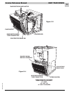
Induced Draft (Combustion) Blower Removal:
Refer to the following directions and Figure 3-1.
To remove the induced draft blower:
1. Disconnect all power to the unit.
2. Shut off and disconnect the gas supply.
3. Remove the plate mounting screws.
4. Slide the induced draft blower out.