


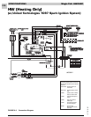


SPECIFICATIONS Magic-Pak: HW/HWC
2-14
SRM-HW/HWC 2/99
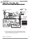
FAILED FLAME SENSE/TRIAL FOR IGNITION
When the pressure switch closes and a 24-volt signal
is sent to pin 5 of the 6-pin ignition wire harness, the
spark ignition cable terminal and pin 4 of the 6-pin
ignition wire harness energize.
1. As spark voltage is supplied to the ignitor elec-
trodes, the gas valve opens and this causes the
burners to ignite.
2. The ignition control continues to energize spark
voltage until a flame sense signal is supplied to the
flame terminal on the ignition control.
3. If a flame sense signal is not received at the flame
terminal on the ignition control, the spark igni-
tion cable terminal remains energized for 10
seconds.
4. After the 10-second trial for ignition, the ignition
control de-energizes the spark ignition cable
terminal and pin 4 of the 6-pin ignition wire harness.
This causes the gas valve to close and the elec-
trode spark to stop.
5. Once the 24-volt signal is sent to pin 4 of the 6-pin
ignition wire harness, a 30-second circulating air
blower “on” delay starts. After the delay is timed
out, the circulating air blower starts.
6. After the spark ignition cable terminal de-ener-
gizes, the ignition control initiates a 30-second
combustion blower inter-purge delay.
7. After 30-second inter-purge, the ignition control
energizes the spark ignition cable terminal and
pin 4 of the 6-pin ignition wire harness. If the flame
sense signal is received at the flame terminal of the
ignition control, the unit continues heat call.
8. If the flame sense signal is not received, the system
goes through three trials following the above
sequence.
9. After three trials, the system goes into lockout and
only the limit switch circuit and pressure switch
circuit remain energized during the 60-minute
lockout period.
10. If the flame sense is lost during the heat cycle, the
gas valve de-energizes immediately and the
system goes into the trial sequence.
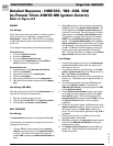
FAN ON
1. When the thermostat is switched to the “FAN ON”
position, the R-G circuit sends a 24-volt signal to
pin 4 of the 5-pin thermostat harness.
2. The 24-volt signal energizes the cooling speed
relay, sending L1 power to the ACB COOL terminal
of the ignition control.
3. L1 power is sent to the circulating air blower
terminal block, causing the circulating air blower
to run in cooling speed.
4. The circulating air blower continues to run in
cooling speed until the thermostat is switched to
“AUTO”, interrupting the R-G circuit.
Note: With the thermostat in the “FAN ON” position
during heat call, ignition control will not energize
the heat speed relay. The circulating air blower
continues to run in cooling speed unless the limit
switch circuit opens, which would cause the heat
speed relay and the induced draft blower relay
to become energized. This would de-energize the
cooling speed relay until either the limit switch
circuit is closed or the thermostat is switched to
the “AUTO” position.