


Service Reference Manual SEQUENCE OF OPERATIONS
2-27
SRM-HW/HWC 2/99
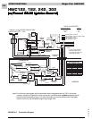
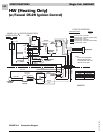
Simplified Sequence - HWC122, 182, 242, 302
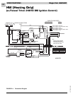
(w/Fenwal 05-29 Ignition Control)
Refer to Figure 2-5
CALL FOR COOLING
1. A call for cooling closes the circuit from R to Y and
G.
2. A 24-volt signal is sent to blower control board
terminal G and to the compressor contactor. The
contactor closes, sending line voltage to the com-
pressor and the outdoor condenser fan.
3. With a 24-volt signal at terminal G on the blower
control board, the circulating air blower starts in
cooling speed 15 seconds later (see note below).
4. When the cooling call is completed, G and Y de-
energize. The contactor opens immediately, stop-
ping the compressor and the outdoor cooling fan.
When G de-energizes, the timer to turn off the
circulating air blower starts. The blower turns off
after 90 seconds (see note below).
FAN ON
1. When the thermostat switch is moved to the “FAN
ON” position, the circuit between R and G closes.
2. The 24-volt signal from G goes to the blower control
board which starts the timer.
3. Fifteen seconds after terminal G on the blower
control board energizes (or immediately after - see
note below), the circulating air blower starts.
4. When terminal G on the blower control board de-
energizes, the timer to turn off the circulating air
blower starts. The blower turns off after 90 seconds
(see note below).
Note: Heatcraft blower control boards have a G “on”
delay of 15 seconds and an “off” delay of 90
seconds. Tridelta blower control boards have no
“on” time delay and a 60 -130 second “off” delay.
CALL FOR HEAT
1. The thermostat energizes the R-W circuit, sending a
24-volt signal to the W wire at the unit.
2. The 24-volt signal is sent to the ignition control,
closing the combustion blower relay and causing the
combustion blower to run.
3. The 24-volt signal is also sent to the blower control
board, starting a 30-second circulation air blower
“on” delay.
4. As the combustion blower reaches full speed, it
closes the pressure switch.
5. A 24-volt signal is sent from the pressure switch to
the ignition control. Following a 30-second pre-
purge delay, this signal energizes the spark termi-
nal.
6. The gas valve solenoid energizes at the same time
as the spark terminal, causing the gas valve to open
and the burners to light.
7. The spark ignitor continues to spark for approxi-
mately six seconds or until flame is sensed by the
flame sensor electrode.
8. The unit will operate normally until the R-W circuit is
de-energized by the thermostat, interrupting the 24-
volt signal to the unit.
9. When the signal is interrupted, the gas valve de-
energizes and closes immediately.
10. The combustion blower relay de-energizes several
seconds later, causing the combustion blower to
stop.
11. The blower control board starts a 90-second
circulating air blower “off” delay.
12. Following the 90-second delay, the circulating air
blower stops.
FLAME SENSE
1. After the spark electrode has lit the main burners,
the ignition control waits approximately six seconds
for a flame sense signal.
2. If a flame sense signal is not received after approxi-
mately six seconds, the ignition control de-ener-
gizes the spark terminal and gas valve.
3. The thermostat R-W circuit sends a 24-volt signal to
the blower control board, starting the circulating air
blower (after a 30-second delay).
4. The unit initiates three trials for ignition (flame
sense) before system lockout.
Detailed Sequence follows