


Service Reference Manual TROUBLESHOOTING
9-7
SRM-HW/HWC 8/99
The following information is found on a capacitor: the MFD (microfarad
rating) and the working voltage. Compare this to the rating plate on the
motor or the information provided with the unit.
The following are some of the problems that could be caused by a
defective or incorrect capacitor:
• Motor overheating (internal thermal overload tripped)
• Motor refuses to start
• Intermittent problems with blown fuses or breaker tripped
• High electrical consumption
• Motor rotates in the wrong direction
• Contactor overheating or melted contacts
• Motor vibration
Any one of the above faults could be attributed to the capacitor. There-
fore, the capacitor must be checked out before a determination is made of
the problem.
In the past, the old method of swinging the meter needle to tell if the
capacitor was good or not could be used. When the terminal of the
capacitor was touched with the meter probes, the meter needle would
swing over than back to zero. If it didn’t, it could be assumed that the
capacitor had failed. There are many problems with this technique.
Swinging the meter needle only proves that the capacitor will take a
charge, but not how much of a charge. In some cases, when a capacitor
starts to break down it still will take a charge (but the number of electrons
that it can hold is greatly reduced). The capacitor must take the correct
charge as originally designed so that the motor will work as it should. A
much more accurate method must be used to determine the condition of
the capacitor before the decision on its condition can be made.
The best method is to use a meter that is capable of reading capacitance.
This gives a very accurate indication of the condition of the capacitor. If a
meter that is able to do this is not available, then another way to deter-
mine the condition of the capacitor must be found.
In order to do this, several things will be needed: a volt ohm meter, an
amp meter and a calculator. A set of test leads will also need to prepared
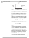
to do this test. Make the test leads with a loop (10 loops) in one of the
leads. The ten loops in the lead will cause the amp meter reading to be
multiplied by “ten”. This will make it much easier to read very low amp
meter readings and will be helpful when doing the following test.
Connect the alligator clips of the test leads to the terminals on the capaci-
tor. Hook the amp meter through the 10 loops of wire on the test lead
(see Figure 9-1 on page 9-8).