


51
On System applications, each Burner Control System is
represented on the Home page by an icon and name. Pressing
the icon allows the user to zoom in on that boiler and see its
specic details. These details are provided on a new page, which
can include additional buttons that display additional detail and
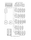
operation information, which itself leads to other pages. The
pages are traversed in a tree structure method, as shown in
Figure 53 on Page 52.
The Control System icons will appear in one of four colors
indicating the boiler status.
• Blue: Normal operation
• Red: Lockout condition
• Gray: Standby mode (burner switch off)
• Gray and crossed out: communication error
(disconnected or powered off)
• Yellow: Preparing for Start-up.
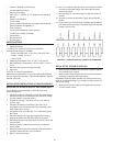
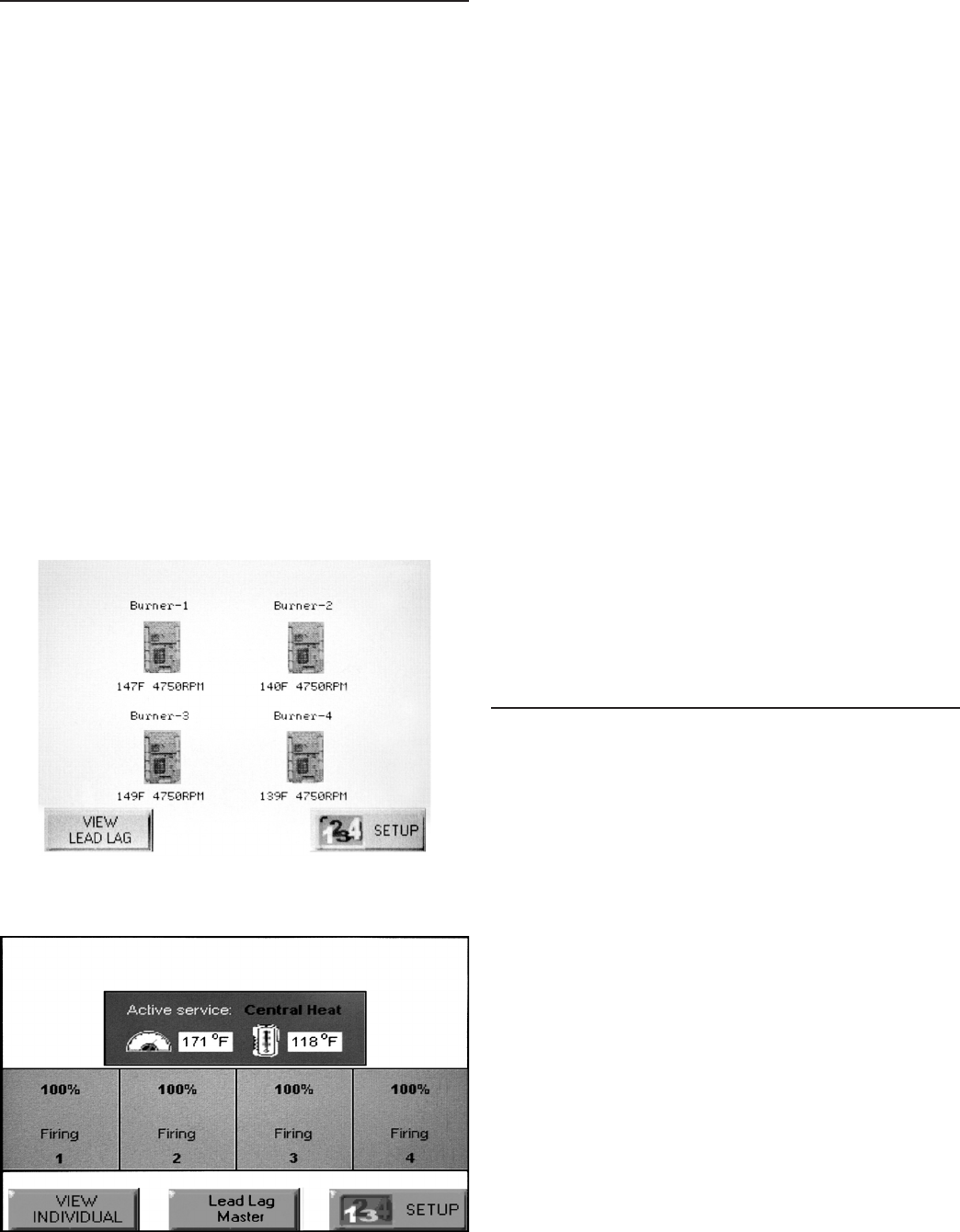
Up to 8 Systems can be displayed on the Home page. The name
of each boiler is displayed next to the Control System icon button.
When Lead Lag is enabled, the system header temperature and
ring rate are displayed for each System. When the burner is in
standby or not ring the ring rate is not displayed.
Note: The boiler name may be cut off on the Home page when
all icons are present.
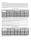
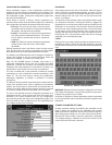
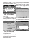
The Home page also includes a System Analysis button that
allows the user to view status information on a system-wide
(that is, multiple boiler) basis. The user can choose which status
information to compare from the Burner Controls in the system.
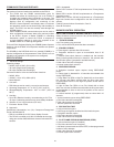
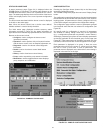
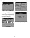
Pressing the Setup button on the Home page displays
miscellaneous setup and diagnostic functions. It also contains
the setup conguration for BAS applications, under the Advanced
Setup button. Pressing the Control System icon opens that
control’s status page.
PAGE NAVIGATION
The Burner Control System OI Displays present information
and options in a paged manner. Pages are displayed in a tree
structure in which the user navigates up and down to arrive at
the desired Function (see Figure 53). The page descriptions
are provided below so that you can understand the purpose of
each and view the selections, parameters, and information that
is available or required on each.
COMMON OI DISPLAY PAGE SYMBOLS
Most pages have a Home button in the top-left corner of the
screen and a Back button in the top-right corner of the screen.
The Home button returns the user to the Home page and
terminates any operation in progress. The Back button returns
the user to the previous page.
Two other icons may be noticed near the boiler name.
A bell will be displayed if the system is in Lockout that reset will
be required.
A padlock will be shown on screens that require a password
to change the parameter. An unlocked padlock indicates the
password has been entered to change the parameter.
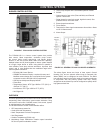
STARTING UP THE S7999B OI DISPLAY
POWER-UP VALIDATION
The Home page will appear and the “Power” LED will be blinking
when the device is properly powered. Select the Setup button to
adjust the contrast and sound as desired.
If the screen is dim, check the pin 1 and 2 wiring connections.
Note: An Advanced Startup screen displays for ve seconds after
power-up before the Home page displays. This screen allows the
user to upgrade the software in the System Display and should
normally be bypassed.
Three LEDs exist for I/O trafc: one for the Ethernet network port
and two for Modbus™ ports. Modbus Com Port 2 is not active
on this device.
1. Make sure the Power and COM1 LEDs are blinking.
2. If the LEDs are not blinking:
• Make sure the proper connections have been made
between the Modbus COM1 Port and the rst controller
device in the Modbus network.
• Ensure proper wiring of the OI Display 9-pin Header
Connections.
3. If connected to a BAS application, COM2 LED will blink
indicating BAS trafc.
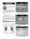
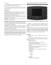
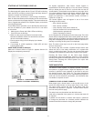
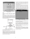
HOME PAGE (S7999B OI DISPLAY)
Make sure a screen similar to Figure 51 appears after the OI
Display has completely powered up.
FIGURE 51. S7999B HOME PAGE
(BOILER 1 IN NORMAL OPERATION)
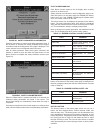
FIGURE 52. S7999B LEAD LAG HOME PAGE