


19
• Auto body shops
• Plastic manufacturing plants
• Furniture renishing areas and establishments
• New building construction
• Remodeling areas
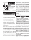
Common household products, pool and laundry products may
contain uorine or chlorine compounds. When these chemicals
come in contact with the boiler, they react and can form strong
acids. The acid can spoil the boiler wall, causing serious damage
and may result in ue gas spillage or boiler water leakage into
the building.
If the above mentioned contaminants and corrosive materials
chemicals are present near the location of the boiler, make sure
to remove the boiler permanently or relocate air inlet and vent
terminations to other areas.
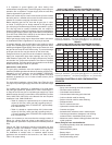
FIELD WIRING
120 VAC POWER SUPPLY WIRING
A dedicated, single phase, 30-60 amp (refer to Table 6 on Page
8) circuit breaker with a grounded neutral should be provided to
supply power to the boilers. Use #10 AWG wire for the 120 VAC
power supply to the boiler. All 120 VAC power supply connections
must be made as shown in Figure 14. These connections
should be made at the rear of the unit where a wiring junction
box is provided. Field installed power supply wiring to the boiler
should be installed in conduit. This conduit and wiring should
be separate from any other conduit/wiring to guard against EMI
(electromagnetic interference).
POWER SUPPLY CHECK
To reduce the possibility of electrical interference with the boiler’s
control system the power supply voltage, polarity and ground must
be checked. Using an AC volt meter check the 120 VAC power
supply wiring from the breaker prior to making power supply
connections at the boiler. Conrm the power supply voltage &
polarity are correct and that an adequate ground connection is
present by performing the three voltage tests below. See Figure
14 for wiring references.
Conrm RMS voltage between:
• H and GND = 108 VAC minimum, 132 VAC maximum.
• N and H = 108 VAC minimum, 132 VAC maximum.
• N and GND = < 1 VAC maximum.
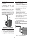
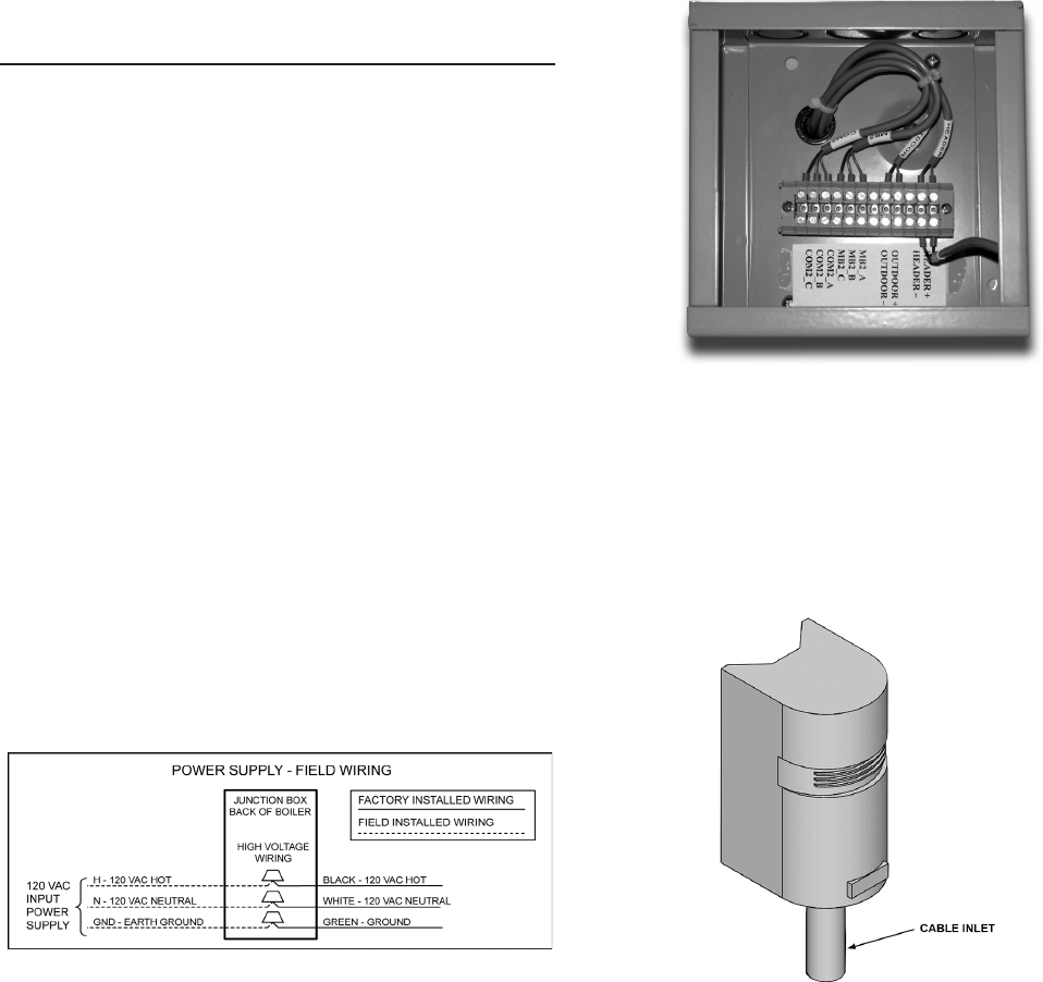
FIGURE 14. FIELD WIRING
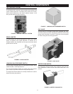
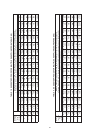
LOW VOLTAGE CONTROL WIRING
1. Header Terminals: In case of Hydronic Boilers, the header
terminals are connected to the hydronic loop header sensor.
Whereas in case of Hot water Boilers the header terminals
are connected to the tank sensor where the temperature can
be sensed. See Figure 15.
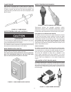
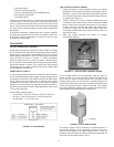
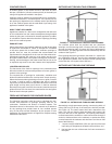
2. Outdoor Terminals: In case of Hydronic Boilers, they are
connected to the outdoor sensors. But in case of Hot water
Boilers, they are not connected. See Figure 15. The outdoor
sensors must be mounted with cable inlet facing down
as shown in Figure 16. The maximum length of the wire
connecting from the boiler to the outdoor sensor must be no
more than 50 feet.
3. MB2 and COM2 terminals are meant for building
management systems.
All low voltage control wiring connections must be made as
shown in Figure 14. These connections should be made at the
rear of the unit where a wiring junction box is provided. Field
installed wiring inside 1/2 inch conduit is installed between the
junction box on the back of the boiler and the temperature probe
and/or eld supplied external control being used. This conduit
and wiring should be separate from any other conduit/wiring to
guard against EMI (electromagnetic interference).
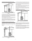
The outdoor sensor must be mounted in a shaded location, to
avoid direct sunlight. It must be atleast 3 feet away from any
exhaust, dryer, bathroom or other building vents. It must be
located on the north side of th building, above the expected snow
line where ice and debris cannot cover it.
FIGURE 15. LOW VOLTAGE CONTROL WIRING
FIGURE 16. OUTDOOR SENSOR