


40
BOILER START UP AND OPERATIONS
IMPORTANT
Only an A.O. Smith Certied Start-up agent must perform the
initial ring of the boiler. At this time the user should not hesitate
to ask the start-up agent any questions regarding the operation
and maintenance of the unit. If you still have questions, please
contact the factory or your local A.O. Smith representative.
Contact Technical Support noted on the back cover for the name
of your closest Certied Start-Up agent.
Lighting and Operating instructions are included with this manual.
By using these instructions, the user may be able to make minor
operational adjustments and save unnecessary service calls.
However the user should not attempt repairs, but should contact
a service technician or gas supplier.
GENERAL
Never operate the boiler without rst making sure the boiler and
system are lled with water, in addition:
• Make sure a temperature and pressure relief valve
is installed in the storage tank for hot water supply
installations.
• Make sure that the boiler and system have been purged
of air and checked for leaks.
Also ensure to check the gas piping for leaks before beginning
the initial ring of the boiler.
FILLING AND PURGING OF HEATING BOILER
INSTALLATION
1. Fast ll system through bypass until pressure approaches
desired system pressure. Close bypass valve and permit
pressure to be established by the pressure reducing valve.
2. Vent all high points in system to purge system of air.
Provisions should be made to permit manual venting of radiators
or convectors.
FILLING HOT WATER SUPPLY BOILER
INSTALLATION
1. Close the system’s drain valve by turning handle clockwise.
2. Open a nearby hot water faucet to permit the air to escape
3. Fully open the cold water inlet pipe valve allowing the boiler
and piping to be lled.
4. Close the hot water faucet as water starts to ow.
PURGING GAS LINE
Gas line purging is required with new piping or systems in which
air has entered.
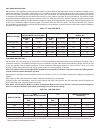
INLET GAS PRESSURE
The inlet gas pressure is measured by removing the 1/8” NPT Plug
located on the upstream side of the supply gas valve, and insert
a 1/8” NPT hose barb tting to be connected to a manometer or
pressure gauge. Once pressure has been checked and/or adjusted,
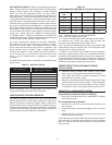
replace the plug and check for leaks. The maximum value specied
in Table 2 on Page 6 must not be exceeded. The minimum values,
shown in Table 2, must be maintained under both load and no load
conditions (static and ring conditions). The combination gas valves
supplied with the boiler are for low pressure service. If upstream
pressure exceeds 14.0” W.C., an intermediate gas pressure
regulator of the lockup type must be installed.
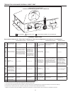
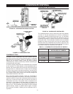
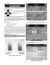
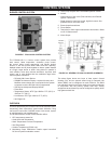
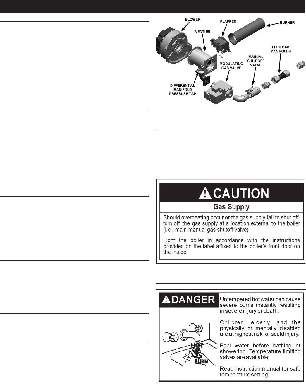
MANIFOLD PRESSURE CONNECTIONS
Take the manifold pressure, refer to Table 2, by removing the pipe
plug and inserting a suitable 1/8” NPT hose barb for connection to
the manometer/pressure gauge. Upon completion of measurements
and adjustments, remove the hose barb and replace the pipe
plug. Check for gas leaks and insure all connections are gas tight,
see Figure 42.
WATER TEMPERATURE REGULATION
FIGURE 42. GAS TRAIN ASSEMBLY