


13
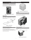
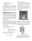
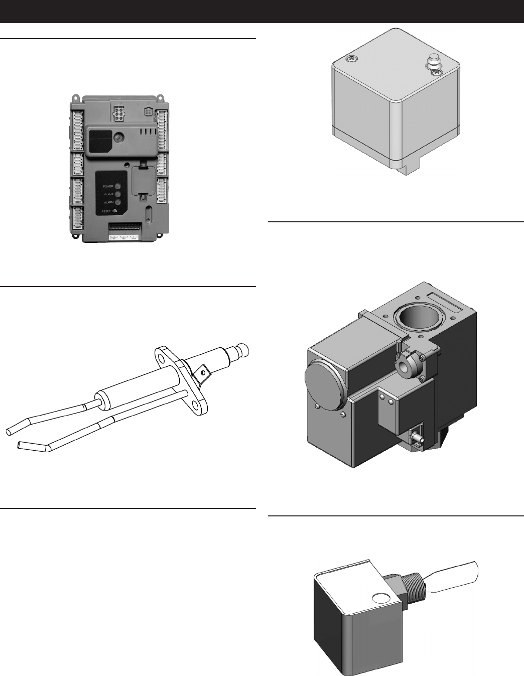
FIGURE 7. LOW/HIGH GAS PRESSURE SWITCH
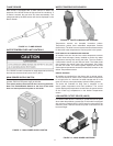
GAS VALVE
The gas valve is a normally closed servo regulated gas valve.
The valve opens only when energized by the burner control and
closes when the power is removed. The burner control supplies
24 volts to the gas valve during operation.
FIGURE 8. GAS VALVE
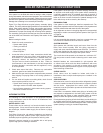
WATER FLOW SWITCH
The water ow switch activates when sufcient water ow has
been established. Switch will not close when water ow is not
present.
FIGURE 9. WATER FLOW SWITCH
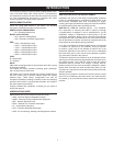
THE CONTROL SYSTEM
The R7910A1138 is a burner control system that provides heat
control, ame supervision, circulation pump control, fan control,
boiler control sequencing, and electric ignition function. It will
also provide status and error reporting.
FIGURE 5. BURNER CONTROL SYSTEM
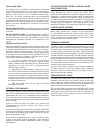
SPARK IGNITER
The spark igniter is a device that ignites the main burner. When
power is supplied to the igniter electrode, an electric arc is
created between the electrode and the ground terminal which
ignites the main burner.
FIGURE 6. SPARK IGNITER
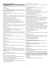
LOW/HIGH GAS PRESSURE SWITCH
This XP boiler is equipped with a low gas pressure switch which
meets the CSD-1 code requirements.
The Low Gas Pressure Switch is normally open and remains
open unless the pressure falls below the preset pressure.
The High Gas Pressure Switch is normally closed and is used to
detect excessive gas pressure.
CONTROL COMPONENTS