


38
6. Use pipe sealing compound compatible with propane gases.
Apply sparingly only to male threads of the pipe joints so that
pipe dope does not block gas ow.
Failure to apply pipe sealing compound as detailed in this
manual can result in severe personal injury, death, or substantial
property damage.
7. Make sure the maximum inlet gas pressure do not exceed
the value specied. Minimum value specied is for input
adjustment only.
Make sure to use two wrenches when tightening gas piping at the
boiler, using one wrench to prevent the boiler gas line connection
from turning. Failure to support the boiler gas connection pipe to
prevent it from turning could damage gas line components. Do
not use wrench on valve body as damage would occur.
GAS PRESSURE REQUIREMENTS
The maximum allowable gas supply pressure for this boiler is
14 inches w.c. (3.5 kPa). Install a positive lock-up gas pressure
regulator in the gas supply line if inlet gas pressure can exceed
14 inches w.c. (3.5 kPa) at any time.
If a positive lock-up regulator is required follow these instructions:
1. Positive lock-up gas pressure regulators must be rated at or
above the input Btu/hr rating of the boiler they supply.
2. Positive lock-up gas pressure regulator(s) should be
installed no closer than 3 feet (1 meter) and no farther than
8 feet (2.4 meters) from the boiler’s inlet gas connection.
3. After installing the positive lock-up gas pressure regulator(s),
an initial nominal supply pressure setting of 7 inches w.c.
(1.7 kPa) while the boiler is operating is recommended and
will generally provide good boiler operation. Some addition
adjustment maybe required later to maintain a steady gas
supply pressure.
4. When installing multiple boilers in the same gas supply
system it is recommended that individual positive lock-up
gas pressure regulators be installed at each unit.
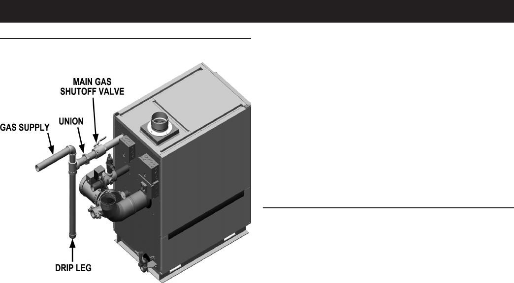
GAS SUPPLY CONNECTIONS
GAS SUPPLY PIPE CONNECTIONS
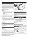
1. Make sure to install ground joint union for servicing.
In Canada – When using manual main shutoff to support the
weight of the piping with valves, ensure that it is identied by the
installer.
2. Install drip leg (sediment trap) per NFPA 54 for US and CAN
B149.1 for Canada.
3. Support the piping with hangers, not by the boiler or its
accessories. The gas valve and blower will not support the
weight of the piping. Failure to comply could result in severe
personal injury, death, or substantial property damage.
4. Purge all air from the gas supply piping.
5. Before setting the boiler in operation, check the boiler and its
gas connection for leaks.
• Disconnect the boiler from the gas supply piping system
during any pressure testing, at a test pressure in excess
of 1/2 PSIG (3.5 kPa)
• The boiler must be isolated from the gas supply piping
system by closing a manual shutoff valve during any
pressure testing, at test pressures equal to or less than
1/2 PSIG (3.5 kPa).
Do not check for gas leaks with an open ame, instead use the
bubble test. Failure to use the bubble test or check for gas leaks
can cause severe personal injury, death, or substantial property
damage.
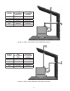
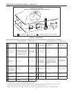
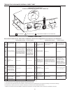
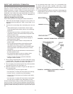
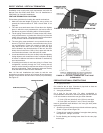
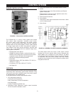
FIGURE 41. GAS SUPPLY PIPING