


49
For example:
— If its add-stage action has been triggered, it will remain in this
condition until either a stage has been added,
Or
— The criteria for its being in an add-stage condition is no longer
met; only then will it take another look around to see what state
it should go to next.
DEFINITIONS
Modulating stage: The modulating stage is the Control System
that is receiving varying ring rate requests to track the load.
First stage: This is the Control System that was turned on rst,
when no slave Control Systems were ring.
Previous stage: The Control System that was added to those
stages that are ring Just prior to the adding of the Control
System that is under discussion.
Next stage: The Control System that will or might be added as
the next Control System to re.
Last stage: The Control System that is ring and that was added
the most recently to the group of slaves that are ring. Typically
this is also the modulating stage, however as the load decreases
then the last-added stage will be at its minimum rate and the
previous stage will be modulating.
Lead boiler: The Lead boiler is the Control System that is the
rst stage to re among those stages which are in the equalize
runtime (Lead/Lag) group. If a boiler is in the “Use rst” group it
may re before the Lead boiler res.
First boiler: A Control System may be assigned to any of three
groups: “Use First”, “Equalize Runtime”, or “Use Last”. If one or
more Control Systems are in the “Use First” category, then one
of these (the one with the lowest sequence number) will always
be the rst boiler to re. If there is no Control System in the “Use
First” category and one or more are in the “Equalize Runtime”
category, then the First boiler is also the Lead boiler.
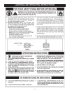
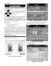
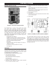
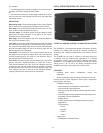
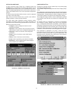
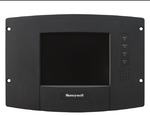
LOCAL OPERATOR INTERFACE: DISPLAY SYSTEM
FIGURE 49. BURNER CONTROL S7999B DISPLAY SYSTEM
The S7999B is a microprocessor-based touchscreen Operator
Interface (OI) display that provide an operator interface for
monitoring and conguring parameters in the Burner Control
system.
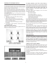
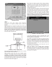
The S7999B can be used to monitor an individual boiler but
is primarily used for multiple boiler applications in a lead/lag
arrangement. COM 2 port is available for Building Automation
applications. The S7999B display is ush mounted into a panel
cutout (8-1/8 in. W x 5-7/8 in. H). Wiring connections to the
S7999B are through a removable 9-pin wiring header.
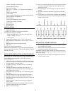
FEATURES
• Individual boiler status, conguration, history, and
diagnostics.
• Allows conguration and monitoring of the Burner Control
Controls burner control sequence, ame signal, diagnostics,
historical les, and faults.
• S7999B OI Display only:
• Allows switching view between multiple boilers
• Allows viewing Lead-Lag Master
• Ethernet port for downloading software upgrades (when
required)
• Real-time data trending analysis and transferring saved
trend data to Excel spreadsheet.
• Audible Alarm
• COM 2 Modbus port for Building Automation System
applications.
• LED indicators:
• Power
• Network
• COM 2
• COM 1
• Model used:
• S7999B1067 has Black Border