


47
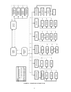
GENERAL OPERATIONAL SEQUENCE
INITIATE
The R7910 enters the Initiate sequence on Initial Power up or:
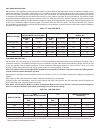
• Voltage uctuations vary less than 20VAC or greater than
30VAC.
• Frequency uctuations vary +/-5% (57 to 63 Hz).
• If Demand, LCI, or Stat interrupt (open) during the Prepurge
Period.
• After the reset button is pressed or fault is cleared at the
displays.
The Initiate sequence also delays the burner motor from being
energized and de-energized from an intermittent AC line input or
control input.
If an AC problem exists for more than 240 seconds a lockout will
occur.
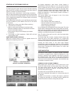
HYDRONIC/CENTRAL HEATING
Start-up sequence central heating request (system in standby):
1. Heat request detected (On Setpoint - On Hysteresis).
2. The CH pump is switched on.
3. After a system Safe Start Check, the Blower (fan) is switched
on after a dynamic ILK switch test (if enabled).
4. After the ILK switch is closed and the purge rate proving fan
RPM is achieved (or High Fire Switch is closed) - prepurge
time is started.
5. When the purge time is complete, the purge fan RPM is
changed to the Lightoff Rate or if used, the damper motor is
driven to the Low Fire Position.
6. As soon as the fan-rpm is equal to the light-off rpm (or the
Low Fire Switch closes), the Trial for Ignition or Pre-Ignition
Time is started.
7. Pre-Ignition Time will energize the ignitor and check for
ame.
8. Trial for Ignition. Specics for timings and device actions are
dened by the OEM or installer.
9. The ignition and the gas valve are switched on.
10. The ignition is turned off at the end of the direct burner
ignition period, or for a system that does use a pilot, at
the end (or optionally at the middle) of the Pilot Flame
Establishing Period (PFEP). For an interrupted pilot system
this is followed by a Main Flame Establishing Period (MFEP)
where the pilot ignites the main burner. For an intermittent
pilot there is no MFEP.
11. The fan is kept at the lightoff rate during the stabilization
timer, if any.
12. Before the release to modulation, the fan is switched to
minimum RPM for the CH Forced Rate and Slow Start
Enable, if the water is colder than the threshold.
13. At the end of the CH-heat request the burner is switched off
and the fan stays on until post purge is complete.
14. A new CH-request is blocked for the forced off time set by
the Anti Short Cycle (if enabled).
15. The pump stays on during the pump overrun time (if
enabled).
16. At the end of the pump overrun time the pump will be
switched off.
6. MAIN FLAME ESTABLISHING PERIOD (MFEP):
a. Lockout Interlock opens (if enabled).
b. Pilot valve terminal is not energized.
c. Main valve terminal is not energized.
d. No ame present at the end of MFEP.
e. Internal system fault occurred.
7. RUN PERIOD:
a. No ame is present, or ame is lost (if enabled-lockout).
b. Lockout Interlock opens) if enabled).
c. IAS Purge and Ignition enabled and the Interlock opens.
d. Pilot terminal energized (if programmed as Interrupted Pilot).
e. Main valve terminal is not energized.
f. Internal system fault occurred.
8. POSTPURGE PERIOD:
a. Preignition Interlock does not close in ve seconds.
b. Pilot Valve terminal is energized.
c. Main Valve terminal is energized.
d. Internal system fault occurred.
e. Flame sensed 240 seconds accumulated time after the RUN
period.
SAFETY SHUTDOWN:
1. If the lockout interlocks open or a sensor designated as a
safety limit are read as defective, Control System will lockout
and the blower motor will be de-energized.
If these open during the ring period, all fuel valves will be de-
energized, the system will complete postpurge, and will lockout
indicated by an alarm.
2. If the pilot ame is not detected by the end of the last (3
number recycle attempt), pilot trial for ignition period, the
pilot valve, and ignition transformer will be de-energized, the
system will complete post purge and will lockout indicated
by an alarm.
3. If the main ame is not detected at the end of the last recycle
attempt of the main ame establishing period, all fuel valves
will be de-energized, the device will complete postpurge,
and will lockout indicated by an alarm.
4. If the ame sensing signal is lost during the run period (if
lockout is selected), all fuel valves will be de-energized within
4 seconds after the loss of the ame signal, the device will
complete postpurge, and will lockout indicate by an alarm.
5. Manual reset is required following any safety shutdown.
Manual reset may be accomplished by pressing the push
button on the device, pressing the remote reset wired into
connector J10, or through an attached display.
Interrupting power to Control System will cause electrical resets,
but does not reset a lockout condition.