


27
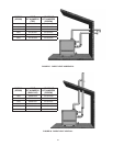
(30.5 m). A maximum of three 90° elbows can be used.
Minimum vertical vent is 7 equivalent feet (2.1 m) for
direct vent installations. Standard minimum vertical vent
length is 7 feet (2.1 m). See Figure 25, Figure 28 thru
Figure 30 for differences between standard and direct
vent installations.
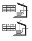
3. An AL 29-4C
®
Vent Vertical Vent Terminal must be used at
the termina tion.
4. Maintain a minimum of 6 feet (2.0 m) separation between
the air intake and the exhaust terminals.
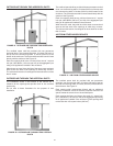
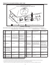
HORIZONTAL INSTALLATION REQUIREMENTS
1. The vent system must terminate with the Through-the-Wall
Termination (TWT) kits. Do not locate the terminal within 8 feet
(2.5 m) of an inside corner of a building or adjacent to outside
walls, shrubs or other such objects that may cause adverse
wind conditions in the immediate area.
2. The TWT should be located not less than 12 inches (305
mm) above grade or, in geographical areas where snow
accumulates, no less than 12 inches (305 mm) above antici-
pated snow line. Ensure that TWT is protected against blockage
which may occur during ice build up or snowstorms. The TWT
should terminate at least 3 feet (1.0 m) above any forced air
inlet within 10 feet (3.0 m), except when the forced air inlet
is the combustion air intake of a direct vent appliance. The
TWT should terminate at least 4 feet (1.2 m) below, 4 feet
(1.2 m) horizontally from or 1 foot (305 mm) above any door,
window or gravity air inlet into any building as provided in the
current edition of the nation al fuel gas code ANSI Z223.1.
In addition, a minimum clearance of 4 feet (1.2 m) horizontally
from, and in no case above or below, unless the 4 feet (1.2
m) of horizontal distance is main tained from electric meters,
gas meters, regulators and relief equip ment.
3. This horizontal exhaust vent system must pitch upward toward
the termination at 1/4 inch per foot (21 mm per meter).
4. The TWT is designed such that the building is protected from
degradation by ue gas and condensate. Howev er, if additional
protection is desired, install against the wall a non-corrosive
metal sheet under the TWT.
5. Due to the normal formation of water vapor in the combustion
process, horizon tal terminations must not be located over
areas of pedestrian or vehicular trafc, (i.e., public walkways
or over areas where condensate could create a nuisance or
hazard). This is especially true in colder climates where ice
buildup is likely to occur. A.O. Smith Corporation will not be
held liable for any personal injury or property damage due to
any dislodg ing of ice.
DIRECT VENT INSTALLATION REQUIREMENTS
The labels in the Direct Vent Kit must be afxed to the boiler in
locations specied by the instruction sheet provided in the kit.
The following are requirements for the Air-Intake Terminal (AIT):
1. The Air-Intake System (AIS) must ter minate with the venting
equipment pro vided with the boiler.
2. The AIT should not be located less than 3 feet (1.0 m) below
any exhaust vent within 10 feet (3.0 m).
3. The total horizontal distance of the AIS from the boiler’s
Blower Adapter to the outside of the “AIT” should not be
greater than 100 equivalent feet (30.5 m) of vent pipe nor
less than 3 feet (1.0 m), excluding elbows. A maximum of 3
elbows, equiva lent to 10 feet (3.0 m) each of pipe may be
used.
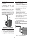
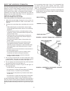
VENTING SUPPORTS
Care must be taken in the installation of the venting system
that adequate support is maintained throughout the installation
process. When extending more than 10 feet (3.0 m) vertically,
vertical support kits are required once every 10 feet (3.0 m) of
vertical run. Vertical support is also re quired immedi ately after
any transi tion (elbow, tee, etc.) to vertical of over 10 feet (3.0 m)
of run and after any offset in the vertical run.
The support brackets (supplied in the Vertical Support Kit)
are to be secure ly fastened to a solid vertical member of the
building using the appropriate fasteners; i.e., wood screws for
wood framing, machine or tapping screws for structural steel
or masonry anchors for solid masonry. The bracket should be
located so that it will not interfere with any joints of the venting
system. The bottom most support bracket should be located
directly above the rst transition from horizontal to vertical.
If a means of support for the brackets is not available and
horizontal vent sections are present, install hanger straps
(made from non-combustible material) as close to the points of
transition as possible. If the horizontal portions of the vent and/or
vent connector are longer than 6 feet (2.0 m), then install hanger
straps every 6 feet (2.0 m) to support the connector.
Do not rivet or screw the straps to the conduit or other wise
puncture the conduit wall. Instead, wrap an extra loop of strap
around the conduit to hold it in position, or attach the strap to
the center screw of the double wall AL 29-4C
®
vent coupling,
if applica ble.
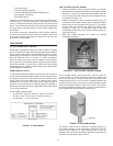
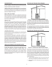
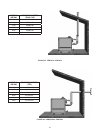
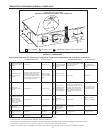
VERTICAL INSTALLATION REQUIREMENTS
1. The vent system must terminate at least 3 feet (1.0 m) and
no more than 6 feet (2.0 m) above the roof line and no closer
than 10 feet (3.0 m) from any wall or verti cal structure. If the
exhaust vent terminal is within 10 feet (3.0 m) of a wall or
parapet, it must extend a minimum of 2 feet (610 mm) above
the wall or parapet, see Figure 25 on Page 28 and Figure
28 on Page 29.
2. For direct vent installations, the total distance of the vent
system from the boiler vent connector to the vertical
vent termination should not exceed 100 equivalent feet
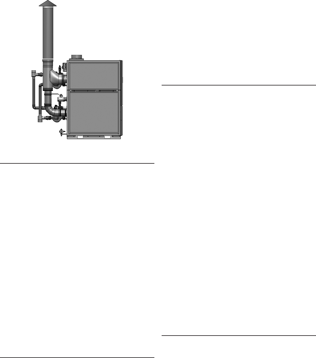
FIGURE 24. PVC/CPVC VENTING - VERTICAL