


18
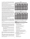
TABLE 8.
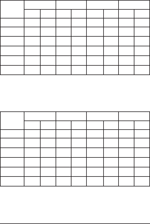
SINGLE UNIT INSTALLATION, SUGGESTED GAS PIPE
SIZING. MAXIMUM EQUIVALENT PIPE LENGTH (IN FEET).
BTU
Input
2” 2-1/2” 3” 4”
Nat Pro Nat Pro Nat Pro Nat Pro
920,000 70 150 175 ----- ----- ----- ----- -----
1,300,000 40 100 100 200 ----- ----- ----- -----
1,700,000 20 60 70 150 200 ----- ----- -----
2,000,000 20 50 50 100 150 ----- ----- -----
2,600,000 10 30 30 70 90 200 ----- -----
3,400,000 ----- ----- 20 40 50 125 200 -----
Natural gas 1000 Btu/ft^
3
, 0.60 specic gravity
@
0.3 in. w.c. pressure drop.
Propane gas 2500 Btu/ft^
3
, 1.50 specic gravity
@
0.3 in. w.c. pressure drop.
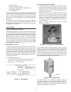
TABLE 9.
SINGLE UNIT INSTALLATION, SUGGESTED GAS PIPE
SIZING. MAXIMUM EQUIVALENT PIPE LENGTH (IN FEET).
BTU
Input
2” 2-1/2” 3” 4”
Nat Pro Nat Pro Nat Pro Nat Pro
920,000 125 200 200 ----- ----- ----- ----- -----
1,300,000 80 175 175 ----- ----- ----- ----- -----
1,700,000 40 100 100 ----- ----- ----- ----- -----
2,000,000 30 80 80 200 200 ----- ----- -----
2,600,000 20 50 50 125 150 ----- ----- -----
3,400,000 10 30 30 70 90 200 ----- -----
Natural gas 1000 Btu/ft^
3
, 0.63 specic gravity
@
0.5 in. w.c. pressure drop.
Propane gas 2500 Btu/ft^
3
, 1.50 specic gravity
@
0.5 in. w.c. pressure drop.
CORROSIVE MATERIALS AND CONTAMINATION
SOURCES
Products to avoid:
• Spray cans containing chloro/uorocarbons
• Permanent wave solutions
• Chlorinated waxes/cleaners
• Chlorine-based swimming pool chemicals
• Calcium chloride used for thawing
• Sodium chloride used for water softening
• Refrigerant leaks
• Paint or varnish removers
• Hydrochloric acid/muriatic acid
• Cements and glues
• Antistatic fabric softeners used in clothes dryers
• Chlorine-type bleaches, detergents, and cleaning
solvents found in household laundry rooms
• Adhesives used to fasten building products and other
similar products
Areas likely to have contaminants:
• Dry cleaning/laundry areas and establishments
• Swimming pools
• Metal fabrication plants
• Beauty shops
• Refrigeration repair shops
• Photo processing plants
It is important to guard against gas valve fouling from
contaminants in the gas ways. Such fouling may cause improper
operation, re or explosion. If copper supply lines are used they
must be approved for gas service.
When local codes require a main manual shut-off valve outside
the boiler jacket, a suitable main manual shut-off valve must be
installed in a location complying with those codes.
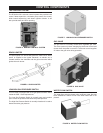
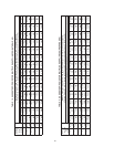
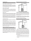
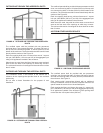
Before attaching gas line be sure that all gas pipe is clean
on inside. To trap any dirt or foreign material in the gas supply
line, a drip leg (or sediment trap) must be incorporated in piping.
The drip leg must be readily accessible and not subject to
freezing conditions. Install in accordance with recommendations
of serving gas supplier. Refer to the current edition of the National
Fuel Gas Code, ANSI Z223.1/NFPA 54 or the Natural Gas and
Propane Installation Code, CAN/CSA B149.1
Size of gas supply piping may be larger than heater connection
on installations where a signicant run of piping is required.
To prevent damage, care must be taken not to apply too much
torque when attaching gas supply pipe to boiler gas inlet. When
installing and tightening gas piping use a second wrench to hold
the gas valve to keep the valve from turning. To prevent damage
to the gas valve do not use pipe wrench on the valve body.
Fittings and unions in gas line must be of metal to metal type.
Apply joint compounds (pipe dope) sparingly and only to the
male threads of pipe joints. Do not apply compound to the rst
two threads. Use compounds resistant to the action of liqueed
petroleum gases. The boiler and its gas connection must be leak
tested before placing the boiler in operation.
GAS SUPPLY LINE SIZING
The gas piping installation must be capable of supplying the
maximum probable gas demand without excessive pressure loss.
Depending on local practices, the ALLOWABLE PRESSURE
LOSS between the gas meter, or service regulator and each
appliance is generally 0.3 or 0.5 inches of water column (0.075
or 0.124 kPa).
For single boiler installation, refer to Table 8 and Table 9 to size
iron pipe or equivalent gas supply line size to be used with single
unit.
For multiple boiler installation or installations of a single boiler
with other gas appliances, please refer to Table 10 and Table 11
on Page 20 to size iron pipe or equivalent gas supply line. These
tables are taken from the current edition of the National Fuel Gas
Code, ANSI Z223.1/NFPA 54 or the Natural Gas and Propane
Installation Code, CAN/CSA B149.1.
• Table 10 is based on a pressure drop of 0.5 inches water
column (0.124 kPa), and a gas with a specic gravity of
0.60 and a heating value of 1,000 BTU/ft
3
, approximately
that of Natural Gas.
• Table 11 is based on a pressure drop of 0.5 inches water
column (0.124 kPa), and a gas with a specic gravity of
1.53 and a heating value of 2,500 BTU/ft3, approximately
that of Propane Gas.
Where it is necessary to use more than the average number of
ttings (i.e., elbows, tees and valves in gas supply line) use a
pipe larger than specied to compensate for increased pressure
drop.
Table 8 and Table 9 shows the maximum equivalent gas pipe
length for a single unit installation. It does not take into account
other appliances that may be connected to the gas line.
For installation of multiple units, or instances where several
appliances are connected to the same line, use Table 10 and
Table 11 for proper sizing.