


17
A discharge pipe from the relief valve should terminate at an
adequate oor drain. Do not thread, plug, or cap the end of
drain line.
The Discharge Pipe:
• Shall not be smaller in size than the outlet pipe size of the
valve, or have any reducing couplings or other restrictions.
• Shall not be plugged or blocked.
• Shall not be exposed to freezing temperatures.
• Shall be of material listed for hot water distribution.
• Shall be installed so as to allow complete drainage of both
the relief valve and the discharge pipe.
• Must terminate a maximum of six inches above a oor
drain or external to the building. In cold climates, it is
recommended that the discharge pipe be terminated at an
adequate drain inside the building.
• Shall not have any valve or other obstruction between the
relief valve and the drain.
Once the boiler is installed and lled with water and the system
is pressurized, manually test the operation of the pressure relief
valve. See the Maintenance Procedures section of this manual
for instructions.
Your local code authority may have other specic safety relief
valve requirements not covered below. If any pressure relief
valve is re placed, the replace ment valve must com ply with the
current version of the ASME Boiler and Pressure Vessel Code,
Section IV (“HEATING BOILERS”).
XB HYDRONIC BOILERS, are shipped with a 50 psi (345 kPa)
pressure relief valve. This relief valve must be in stalled in the
water outlet as near to the boiler as possi ble.
XW HOT WATER BOILERS, are shipped with a 125 psi (860
kPa) pressure relief valve that must be in stalled in the water out-
let as near to the boil er as possi ble.
This ASME-rated valve has a discharge capacity that exceeds
maximum boiler input rating and a pres sure rating that does not
exceed maxi mum working pres sure shown on boiler rating plate.
In addition, a CSA design-certied and ASME-rated tempera ture
and pressure (T&P) relief valve must be installed on each and
every water storage tank in hot water supply system. The T&P
relief valve must comply with appli cable construction provisions
of Standard for Relief Valves for Hot Water Supply Systems, ANSI
Z21.22 or CSA 4.4. T&P re lief valve must be of automatic reset
type and not embody a single-use type fusible plug, cartridge or
linkage.
T&P relief valve should have a temperature rating of 210°F
(99°C), a pressure rating not exceeding lowest rated working
pressure of any system compo nent, and a discharge capacity
exceeding total input of water boilers supply ing water to storage
tank.
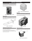
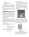
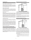
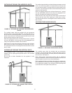
Locate the T&P relief valve (a) in the top of the tank, or (b) in
the side of the tank on a centerline within the upper 6 inches
(152 mm) of the top of the tank, see Figure 78 and Figure 79.
The tapping should be threaded in accordance with the current
edition of the Standard for Pipe Threads, General Purpose
(inch), ANSI/A SME B1.20.1. The location of, or in tended location
for, the T&P relief valve should be readily accessible for servicing
or replacement.
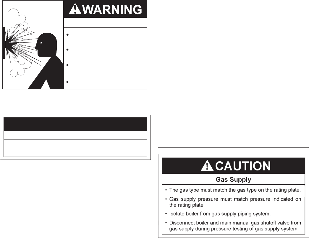
GAS CONNECTIONS
Make sure the gas on which boiler is to operate is same as that
specied on the rating plate. Do not install boiler if equipped for a
different type of gas. Consult your gas supplier.
This boiler is not intended to operate at gas supply pressure
other than shown on the rating plate. A lock-up or positive shut-
off type regulator must be installed in gas supply line. For proper
gas regulation the lock-up style regulators must be installed no
closer than a minimum of 3 feet from the boiler and a maximum
of 8 feet away from the boiler. Exposure to higher gas supply
pressure may cause damage to gas valves which can result in
re or explosion. If overpressure has occurred such as through
improper testing of gas lines or emergency malfunction of supply
system, the gas valves must be checked for safe operation.
Make sure that the outside vents on supply regulators and the
safety vent valves are protected against blockage. These are
parts of the gas supply system, not boiler. Vent blockage may
occur during ice build-up or snowstorms.
The boiler must be isolated from the gas supply piping system by
closing its main manual gas shut off valve during any pressure
testing of the gas supply piping system at test pressures equal
to or less than 1/2 psig.
Disconnect the boiler and its main manual gas shut-off valve
from the gas supply piping during any pressure testing of the
gas supply system over 1/2 psig. The gas supply line must be
capped when not connected to the boiler.
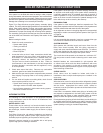
CAUTION
• Pressure Relief Valve discharge pipe must
terminate at adequate drain.
Water Damage Hazard
Explosion Hazard
Relief Valve must comply with
ASME code.
Properly sized Relief Valve must
be installed in opening provided.
Can result in overheating and
excessive tank pressure.
Can cause serious injury or death.