


48
LEAD LAG (LL) MASTER GENERAL OPERATION
The XP Boiler is a multiple burner application and it works on
the basis of the Lead Lag Operation. The XB Boiler is factory
congured for Hydronic/Central Heating application, whereas the
XW Boiler is factory congured for Domestic Hot Water application.
The LL master coordinates the ring of its slave Control Systems.
To do this it adds and drops stages to meet changes in load, and
it sends ring rate commands to those that are ring.
The LL master turns the rst stage on and eventually turns the
last stage off using the same criteria as for any modulation
control loop:
• When the operating point reaches the Setpoint minus the
On hysteresis, then the rst Control System is turned on.
• When the operating point reaches the Setpoint plus the Off
hysteresis then the last slave Control System (or all slave
Control Systems) are turned off.
The LL master PID operates using a percent rate: 0% is a
request for no heat at all, and 100% means ring at the maximum
modulation rate.
This ring rate is sent to the slaves as a percentage, but this is
apportioned to the slave Control Systems according to the rate
allocation algorithm selected by the Rate allocation method
parameter.
For some algorithms, this rate might be common to all slave
Control Systems that are ring. For others it might represent the
total system capacity and be allocated proportionally.
For example, if there are 4 slaves and the LL master's percent
rate is 30%, then it might satisfy this by ring all four slaves at
30%, or by operating the rst slave at 80% (20% of the system’s
capacity) and a second slave at 40% (10% of the system’s
capacity).
The LL master may be aware of slave Control System’s minimum
ring rate and use this information for some of its algorithms,
but when apportioning rate it may also assign rates that are less
than this. In fact, the add-stage and drop-stage algorithms may
assume this and be dened in terms of theoretical rates that are
possibly lower than the actual minimum rate of the Burner Control
System. A Control System that is ring and is being commanded
to re at less than its minimum modulation rate will operate at
its minimum rate: this is a standard behavior for a Buner control
system in stand-alone (non-slave) mode.
If any slave under LL Master control is in a Run-Limited condition,
then for some algorithms the LL master can apportion to that
stage the rate that it is actually ring at. Additionally when a
slave imposes its own Run-limited rate, this may trigger the LL
Master to add a stage, if it needs more capacity, or drop a stage
if the run-limiting is providing too much heat (for example if a
stage is running at a higher-than commanded rate due to anti-
condensation).
By adjusting the parameters in an extreme way it is possible
to dene add-stage and drop-stage conditions that overlap or
even cross over each other. Certainly it is incorrect to do this,
and it would take a very deliberate and non-accidental act to
accomplish it. But there are two points in this:
1. LL master does not prevent it, and more important;
2. It will not confuse the LL master because it is implemented
as a state machine that is in only one state at a time;
DOMESTIC HOT WATER
Start-up sequence DHW-request (system in standby):
1. Heat request detected (either DHW Sensor Only, DHW
Sensor and Remote Command or DHW Switch and Inlet
Sensor, whichever applies).
2. The pump is switched on (after the DHW Pump Start Delay).
3. After a system Safe Start Check, the Blower (fan) is switched
on after a dynamic ILK switch test (if enabled).
4. After the ILK switch is closed and the purge rate proving fan
RPM is achieved (or High Fire Switch is closed) - prepurge
time is started.
5. When the purge time is complete, the purge fan RPM is
changed to the Lightoff Rate or if used, the damper motor is
driven to the Low Fire Position.
6. As soon as the fan-rpm is equal to the light-off rpm (or the
Low Fire Switch closes), the Trial for Ignition or Pre-Ignition
Time is started (depending on conguration).
7. Pre-Ignition Time will energize the ignitor and check for
ame.
8. Trial for Ignition. Specics for timings and device actions are
dened by the OEM or installer.
9. The ignition and the gas valve are switched on.
10. The ignition is turned off at the end of the direct burner
ignition period, or for a system that does use a pilot, at
the end (or optionally at the middle) of the Pilot Flame
Establishing Period (PFEP). For an interrupted pilot system
this is followed by a Main Flame Establishing Period (MFEP)
where the pilot ignites the main burner. For an intermittent
pilot there is no MFEP.
11. The fan is kept at the lightoff rate during the stabilization
timer, if any.
12. Before the release to modulation, the fan is switched to
minimum RPM for the DHW Forced Rate and Slow Start
Enable, if the water is colder than the threshold.
13. At the end of the DHW-heat request the burner is switched
off and the fan stays on until post purge is complete.
14. A new DHW-request is blocked for the forced off time set by
the Anti Short Cycle (if enabled).
15. The pump stays on during the pump overrun time (if
enabled).
16. At the end of the pump overrun time the pump will be
switched off.
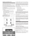
LEAD LAG
Burner Control System devices contain the ability to be a stand-
alone control, operate as a Lead Lag Master control (which also
uses the burner control function as one of the slaves), or to
operate solely as a slave to the lead lag system.
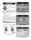
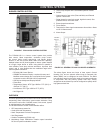
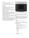
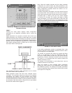
Control System devices utilize two ModBus™ ports (MB1
and MB2) for communications. One port is designated to
support a system S7999B display and the other port supports
communications from the LL Master with its slaves.
The Lead Lag master is a software service that is hosted by a
Control System. It is not a part of that control, but is an entity
that is “above” all of the individual burner controls (including the
one that hosts it). The Lead Lag master sees the controls as a
set of Modbus devices, each having certain registers, and in this
regard it is entirely a communications bus device, talking to the
slave buner controls via Modbus.
The LL master uses a few of the host Buner Control's sensors
(header temperature and outdoor temperature) and also the
STAT electrical inputs in a congurable way, to provide control
information.