


16
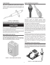
CIRCULATING PUMP
A circulating pump is used when a system requires a circulating
loop or there is a storage tank used in conjunction with the boiler.
Install in accordance with the current edition of the National
Electrical Code, NFPA 70 or the Canadian Electrical Code,
CSA C22.1. All bronze circulating pumps are recommended
for use with commercial boilers. Some circulating pumps are
manufactured with sealed bearings and do not require further
lubrication. Some circulating pumps must be periodically oiled.
Refer to the pump manufacturer’s instructions for lubrication
requirements.
XB HYDRONIC BOILERS: The circulating pump is not provided
on standard models (optional) and must be obtained and installed
in the eld.
XW HOT WATER BOILERS: The circulating pump is integral to
the XW models. This pump has been lubricated at the factory,
and future lubrication should be in accordance with the motor
manufacturer’s instructions provided as a supplement to this
manual.
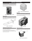
PRIMARY SYSTEM CONTROL
All XP boiler installations require a “Primary System Control” that
senses and reacts to water temperature inside the storage tank
on domestic water applications or in the return line on primary/
secondary hydronic heating systems. The Primary System
Control will activate and deactivate boiler heating cycles based
on its setpoint and current system water temperature. There are
three suitable methods to congure a Primary System Control.
One of these three methods must be used.
1. The Primary System Control can be the boiler’s
control system working with the factory supplied Header
Sensor, installed inside the storage tank on domestic water
applications or in the return line on primary/secondary
hydronic heating systems.
2. Alternatively, the Burner Control system can be used
as a Primary System Control. It will also provide boiler status
and error reporting. Multiple boilers can be joined together
to heat a system instead of a single, larger burner or boiler.
Using boilers in parallel is more efcient, costs less, reduces
emissions, improves load control, and is more exible than
the traditional large boiler.
3. MB2 and COM2 ports can be used for Building
Management Systems.
INTERNAL CONTAMINANTS
The hydronic system must be internally cleaned and ushed
after a new or replacement boiler has been installed, to remove
contaminants that may have accumulated during installation.
This is extremely important when a replacement boiler is installed
into an existing system where Stop Leak or other boiler additives
have been used.
Failure to clean and ush the system can produce acid
concentrations that become corrosive, and leads to heat
exchanger failure.
All hot water heating systems should be completely ushed with
a grease removing solution to assure trouble-free opera tion. Pipe
joint compounds, soldering paste, grease on tubing and pipe all
tend to contaminate a system
Failure to ush contaminants from a system can cause solids
to form on the inside of boiler exchangers, create excessive
blockage of water circulation, deterioration of the pump seals
and impellers.
HOT WATER BOILER SYSTEM - GENERAL WATER
LINE CONNECTIONS
Piping diagrams will serve to provide the installer with a
reference for the materials and methods of piping necessary for
installation. It is essential that all water piping be installed and
connected as shown on the diagrams. Check the diagrams to
be used thoroughly before starting installation to avoid possible
errors and to minimize time and material cost. It is essential that
all water piping be installed and connected as shown on the
diagrams. See Figure 78 on Page 80 and Figure 79 on Page 81.
CLOSED WATER SYSTEMS
Water supply systems may, because of code requirements
or such conditions as high line pressure, among others, have
installed devices such as pressure reducing valves, check
valves, and back ow preventers. Devices such as these cause
the water system to be a closed system.
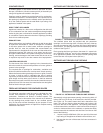
THERMAL EXPANSION
As water is heated, it expands (thermal expansion). In a closed
system the volume of water will increase when it is heated. As the
volume of water increases there will be a corresponding increase
in water pressure due to thermal expansion. Thermal expansion
can cause premature failure (leakage). This type of failure is not
covered under the limited warranty. Thermal expansion can also
cause intermittent Temperature-Pressure Relief Valve operation:
water discharged from the valve due to excessive pressure build
up. This condition is not covered under the limited warranty.
The Temperature-Pressure Relief Valve is not intended for the
constant relief of thermal expansion.
A properly sized thermal expansion tank must be installed on
all closed systems to control the harmful effects of thermal
expansion. Contact a local plumbing service agency to have a
thermal expansion tank installed.
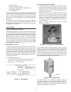
PRESSURE RELIEF VALVE
An ASME rated pressure relief valve is furnished with the boiler.
A tting for the relief valve is provided in the top of the boiler.
Never operate the heating elements without being certain the
boiler is lled with water and a properly sized pressure relief
valve is installed in the relief valve opening provided.
The pressure rating of the relief valve should be equal to or less
than the rated pressure capacity of any component in the system
including the boiler. Should the valve need to be replaced, call
the toll free phone number listed on the back of this manual for
further technical assistance