


15
GENERAL
If the system is to be lled with water for testing or other purposes
during cold weather and before actual operation, care must be taken
to prevent freezing of water in the system. Failure to do so may cause
the water in the system to freeze with resulting damage to the system.
Damage due to freezing is not covered by the warranty.
Figure 78 on Page 80 shows a typical primary, secondary piping
method. This is the preferred piping method for most stainless steel
boilers. Other piping methods, however, may provide good system
operation. A prime concern when designing heating systems is the
maintenance of proper ow through the unit during boiler operation.
The secondary pump should be sized per the recommended ow
rate of the boiler, see Dimension and Capacity Data section in this
manual.
Before locating the boiler:
1. Check for nearby connection to:
• System water piping
• Venting connections
• Gas supply piping
• Electrical power
2. Locate the boiler so that if water connections should leak,
water damage will not occur. When such locations cannot
be avoided, it is recommended that a suitable drain pan,
adequately drained, be installed under the appliance.
The pan must not restrict combustion air ow. Under no
circumstances is the manufacturer to be held responsible
for water damage in connection with this appliance, or any
of its components.
3. Check area around the boiler. Remove any combustible
materials, gasoline and other ammable liquids.
4. Make sure the gas control system components are protected
from dripping or spraying water or rain during operation or
service.
5. If a new boiler will replace an existing boiler, check for and
correct system problems, such as:
• System leaks causing oxygen corrosion or heat
exchanger cracks from hard water deposits.
• Lack of freeze protection in boiler water causing system
and boiler to freeze and leak.
HYDRONIC SYSTEM
The following is a brief description of the equipment required
for the installations noted in this manual. All installations must
comply with local code.
WATER SUPPLY LINE
These boilers can be used only in a forced circulation hot water
heating system. Since most forced circulation systems will be of
the closed type, install the water supply line as shown on piping
diagram.
Fast lling of large pipe, old radiator installations and pressure
purging of series loop systems (where high pressures are not
available) requires bypassing of the pressure reducing valve.
Gener ally, pressure purging is not possible with a well pump
system. High point air venting is essential.
If the system is of the open type, a pressure reducing valve will not
be required as the water supply to the system will be controlled by
a manu ally operated valve. An overhead surge tank is required. A
minimum pressure of 15 psi (100 kPa) must be maintained on the
boiler at all times to ensure avoidance of potential damage to the
boiler which may not be covered by the warranty.
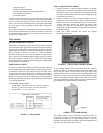
EXPANSION TANK
If the system is of the closed type, install an expansion tank. The
sizing of the expansion tank for a closed system is very important and
is directly related to the total water volume of the system.
An air separator as shown in the piping diagrams is recommended
especially for modern commercial hydronic systems. See Figure 78
on Page 80.
VENT VALVES
It is recommended that automatic, loose key or screw-driver type
vent valves be installed at each convector or radiator.
SYSTEM HEADERS
Split systems with individual supply and return lines from the
boiler room should normally have this piping connected to
supply and return manifold headers near the boiler. To achieve
good water distribution with maximum pressure drop for sever al
circuits, manifolds should be larger than system mains.
The circuits should be spaced on the heater at a minimum of 3”
(76 mm) center to center. Install a balancing cock in each return
line.
Manifold headers are recommended for split systems with
or without zone valves and also those installations with zone
circulators. If the system is to be split at remote points, good
practice requires special attention be given to main pipe sizing to
allow balancing of water ow.
CHECK VALVES
Check valves must be installed to isolate each boiler in
installations where multiple boilers/pumps are installed in the
same zone.
COOLING PIPING
When the boiler is used in conjunction with a refrigeration system
it must be installed so that the chilled medium is piped in parallel
with the boiler. Appropriate ow control valves, manual or
motorized, must be provided to prevent the chilled medium from
entering the boiler.
If the boiler is connected to chilled water piping or its heating coils
are exposed to refrigerated air, the boiler piping system must be
equipped with ow valves or other automatic means to prevent
gravity circulation through the boiler during the cooling cycle.
Primary/secondary pumping of both the chiller(s) and the boiler(s) is
an excellent winter-summer change-over method, because cooling
ow rates are so much more than heating ow rates. In this way each
system (heating or cooling) is circulated independently.
BOILER INSTALLATION CONSIDERATIONS