


50
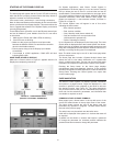
10. Drill 1/4 in. holes through the panel at the marked locations
and secure the power supply with the two #6-32 screws
and nuts provided.
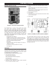
11. Remove the 9-pin connector plug from the back of the OI
Display.
12. Wire the connector to the power supply and the RS-485
cables.
13. Ensure the 9-pin connector plug is aligned with the header
pins when inserting the 9-pin connector plug back onto the
Display. Secure rmly.
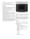
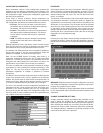
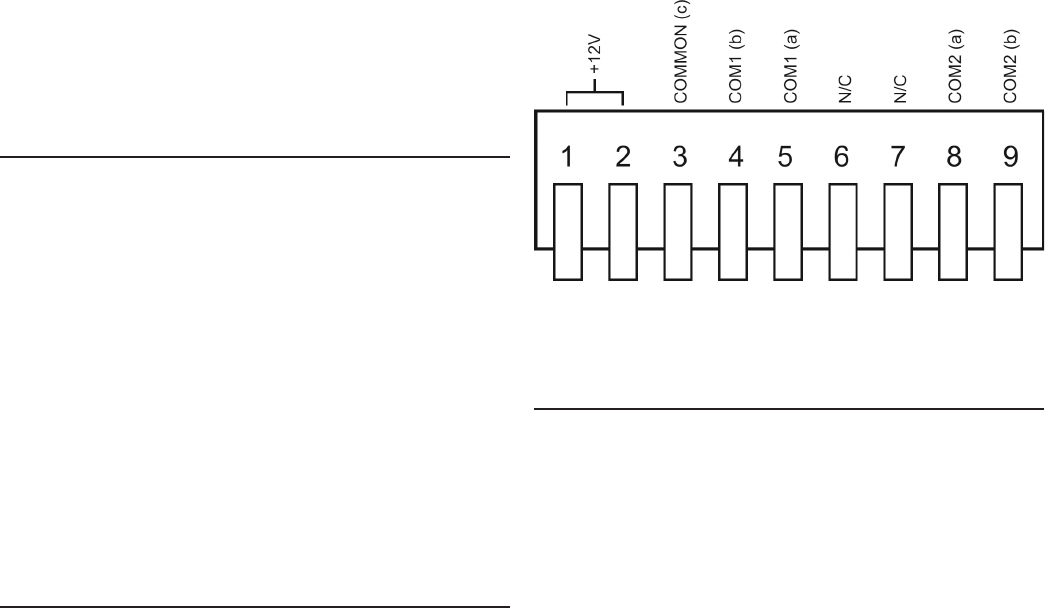
FIGURE 50. S7999B OI DISPLAY CONNECTOR TERMINALS
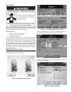
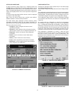
QUICK SETUP (S7999B OI DISPLAY)
1. Make sure the S7999B 9-pin connector is properly aligned
and pressed rmly in place.
2. Make sure the wires between the 9-pin connector and the
controller are properly wired and secure.
WARNING: Electrical Shock Hazard. Can cause severe injury,
death or equipment damage. Line voltage is present at the 120
VAC power supply.
3. Make sure the power supply is connected securely to the
120 VAC power source.
• Allows for lead/lag commissioning.
• Locates attached boiler(s).
• Allows boiler naming.
• Color 3.5 in. x 4.625 in. (5.7 in. diagonal) user interface
display.
• Graphic user interface.
• Touch screen.
• Communication between the OI Displays and the Burner
Control Systems uses Modbus™.
• Flush mounting.
• Touch screen disable for screen cleaning.
• 12 VDC power supply (included).
• Screen saver.
• Contrast control.
• Volume control.
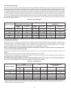
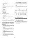
SPECIFICATIONS
1. Electrical Ratings:
+12 VDC input, maximum of 500 mA current drain.
Included Power Supply for S7999B:
• Inputs: 85 to 264 VAC, 47 to 63 Hz; 120 to 370 VDC.
• Output: 12 VDC; 0 to 2.1 A.
• Power: 25 W.
2. Operating Temperature: 32°F to 122°F (0°C to 50°C)
3. Storage/Shipping Temperature: -40°F to 158°F (-40°C to
70°C).
4. Humidity: 85% maximum relative humidity.
5. Approvals:
FCC Part 15, Class A Digital Device
Underwriter’s Laboratories, Inc. (UL) Component Recognized
(for non-continuous operation): File Number MH20613 (MCCZ)
Canada: ICES-003
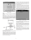
INSTALLATION INSTRUCTIONS (S7999B OI DISPLAY)
MOUNTING THE S7999B OI DISPLAY AND POWER SUPPLY
The OI Display can be mounted on the door panel of an
electrical enclosure.
1. Select the location on the door panel to mount the display;
note that the device will extend into the enclosure at least
one inch past the mounting surface.
2. Provide an opening in the panel door 8-1/8 in. wide by
5-7/8 in. high.
3. Place the OI Display in the opening and use it as a
template to mark the location of the four mounting screw
holes. Remove the device.
4. Using pilot holes as guides, drill 1/4 in. holes through the
door panel.
5. Place the display in the opening, aligning the mounting
holes in the device with the drilled holes in the panel.
6. Secure the display to the panel with four #6-32 screws and
nuts provided.
7. Select a location inside the enclosure for mounting the
power supply.
8. Using the power supply as a template, mark the locations
of the two mounting holes in the enclosure.
9. Remove the power supply.