


35
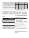
DIRECT VENTING: VERTICAL TERMINATION
Installation must comply with local requirements and with the
National Fuel Gas Code, ANSI Z223.1 for U.S. installations or
CSA B149.1 for Canadian installations.
VENT/AIR TERMINATION LOCATIONS:
Follow these guidelines for locating the vent/air terminations:
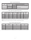
1. Make sure the total length of piping for vent or air do not
exceed the limits mentioned in Table 14 and Table 15 on
Page 36.
2. The vent must terminate at least 3 feet above the highest
place in which the vent penetrates the roof and at least 2
feet above any part of a building within 10 feet horizontal.
3. The air piping must terminate in a down-turned 180° elbow,
using a mesh screen, no further than 2 feet (0.6 m) from the
center of the vent pipe. This placement avoids recirculation
of ue products into the combustion air stream.
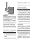
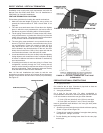
4. The vent piping must terminate in an up-turned rain cap as
shown in Figure 35. When the vent termination uses a rain
cap as illustrated in Figure 35, maintain at least 36" (914
mm) above the air inlet. The air inlet pipe and vent pipe
can be located in any desired position on the roof, but must
always be no further than 2 feet (0.6 m) apart and with the
vent termination at least 1 foot above the air intake.
5. Locate terminations so they are not likely to be damaged by
foreign objects, such as stones or balls, or subject to buildup
of leaves or sediment and also not blocked or restricted by
snow accumulation.
6. If installing both intake air and vent piping in a Direct Vent
conguration vertically through the roof; ensure that all
exterior vertical clearance requirements shown in Figure 35
are being maintained. These clearances and those cited by
local and national codes must be maintained.
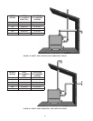
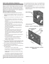
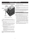
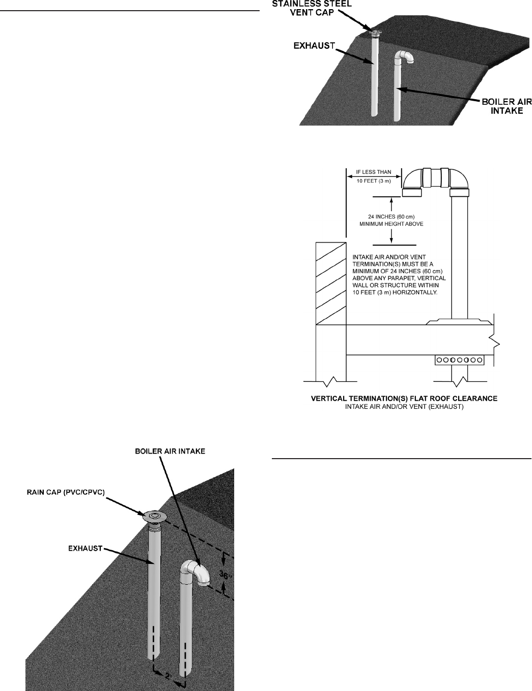
Note: On at roof installations the intake air and the vent
terminations must be a minimum of 24 inches (60 cm) above any
parapet, vertical wall or structure within 10 feet (3 m) horizontally.
See Figure 37.
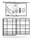
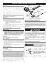
FIGURE 35. PVC/CPVC AIR/VENT TERMINATION -
VERTICAL
PREPARE ROOF/WALL PENETRATIONS
1. Air pipe penetration:
Cut a hole for the air pipe. Size the air pipe hole as close as
desired to the air pipe outside diameter.
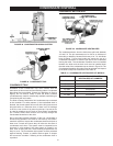
2. Vent pipe penetration:
Cut a hole for the vent pipe. For either combustible or
noncombustible construction, size the vent pipe hole with at least
a 1/2 inch clearance around the vent pipe outer diameter:
• 7½ inch (178 mm) hole for 6 inch (152 mm) vent pipe
• 8½ inch (203 mm) hole for 7 inch (178 mm) vent pipe
Insert a galvanized metal thimble in the vent pipe hole (when
required by local codes).
3. Space the air and vent holes to provide the minimum spacing
shown in Figure 35 and Figure 36.
4. Follow all local codes for isolation of vent pipe when passing
through oors, ceilings, and roofs.
5. Provide ashing and sealing boots sized for the vent pipe
and air pipe.
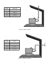
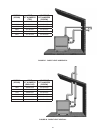
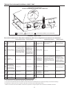
FIGURE 36. STAINLESS STEEL AIR/VENT TERMINATION -
VERTICAL
FIGURE 37. VERTICAL TERMINATION - FLAT ROOF
CLEARANCES