


036-21410-001-A-0502
50 Unitary Products Group
GUIDE SPECIFICATIONS
GENERAL
Units shall be manufactured by York International Unitary
Products Group in an ISO 9001 certified facility.
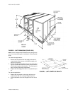
York's Sunline Magnum™ units are convertible single pack-
age units. All models have dual independent refrigerant cir-
cuits for efficient part load operation and maximum comfort
control. Although the units are primarily designed for curb
mounting on a roof, they can also be slab-mounted at ground
level or set on steel beams above a finished roof. Cooling
only, cooling with gas heat and cooling with electric heat
models are available with a wide variety of factory-mounted
options and field-installed accessories to make them suitable
for almost every application. All units are self-contained and
assembled on full perimeter base rails with holes in the four
corners for overhead rigging. Every unit is completely piped,
wired, charged and tested at the factory to simplify the field
installation and to provide years of dependable operation. All
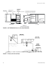
models (including those with an economizer) are suitable for
either bottom or horizontal duct connections. Models with
power exhaust are suitable for bottom duct connections only.
For bottom duct, remove the sheet metal panels from the
supply and return air openings through the base of the unit.
For horizontal duct, replace the supply and return air panels
on the rear of the unit with a side duct flange accessory. All
supply air blowers are equipped with a belt drive that can be
adjusted to meet the exact requirements of the job.
Each unit shall have 4 condenser fan motors. A high speed
drive accessory is available for applications with a higher
CFM and/or static pressure requirement. All compressors
include crankcase heat and internal pressure relief. Every
refrigerant circuit includes an expansion valve, a liquid line fil-
ter-drier, a discharge line high pressure switch and a suction
line with a freezestat and low pressure/loss of charge switch.
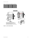
The unit control circuit includes a 75 VA transformer, a 24-volt
circuit breaker and a relay board with two compressor lockout
circuits, a terminal strip for thermostat wiring, plus an addi-
tional set of pin connectors to simplify the interface of addi-
tional field controls. All units have long lasting powder paint
cabinets with 750 hour salt spray test approval under ASTM-
B117 procedures. All 208/230 and 460-volt models are ETL
approved. All 208/230 and 575-volt models are CGA
approved. All models include a 1-year limited warranty on the
complete unit. Compressors and electric heater elements
carry an additional 4-year warranty. Aluminized steel tubular
heat exchangers carry an additional 9-year warranty.
DESCRIPTION
Units shall be factory-assembled, single packaged, DJ***N
Electric Cooling/Gas Heat, DJ***C/E Electric Cooling/
Optional Electric Heat, designed for outdoor mounted instal-
lation. The 15,17.5, and 20 ton units shall have minimum
EER ratings of 11.1. The 25 ton unit shall have a minimum
EER rating of 10.5.
They shall have built-in field convertible duct connections for
down discharge supply/return or horizontal discharge supply/
return, and be available with factory installed options or field
installed accessories. The units shall be factory wired, piped,
charged with R-22 refrigerant and factory tested prior to ship-
ment. All unit wiring shall be both numbered and color coded.
All units shall be manufactured in a facility certified to ISO
9001 standards and the cooling performance shall be rated in
accordance with DOE and ARI test procedures. Units shall be
ETL & CGA listed, classified to ANSIZ21.47 standards, UL
1995/CAN/CSA No. 236-M90 conditions.
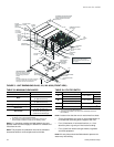
UNIT CABINET
Unit cabinet shall be constructed of G90 galvanized steel,
with exterior surfaces coated with a non-chalking, powdered
paint finish, certified at 750 hours salt spray test per ASTM-
B117 standards. Indoor blower section shall be insulated with
a minimum 1/2" thick insulation, coated on the airside. Alumi-
num foil faced insulation shall be used in the furnace com-
partment and be fastened with ridged fasteners to prevent
insulation from entering the air stream. Cabinet panels shall
be "large" size, easily removable for servicing and mainte-
nance. Full perimeter base rails shall be provided to assure
reliable transit of equipment, overhead rigging and proper
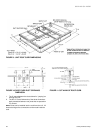
sealing on roof curb applications. Disposable 2" filters shall
be furnished and be accessible through a removable access
door, sealed airtight. Units filter track shall be designed to
accommodate either 1" or 2" filters. Fan performance mea-
suring ports shall be provided on the outside of the cabinet to
allow accurate air measurements of evaporator fan perfor-
mance without removing panels or creating air by-pass of the
coils. Condensate pan shall be internally sloped and conform
to ASHRAE 62-89 self-draining standards. Condensate con-
nection shall be a minimum of 1" I.D. female and be a ridged
mount connection. Unit shall incorporate a fixed outdoor air
damper with an outdoor air intake opening covered with a
bird screen and a rain hood painted to match the exterior of
the unit.
INDOOR (EVAPORATOR) FAN ASSEMBLY
Fan shall be a belt drive assembly and include an adjustable-
pitch motor pulley. Job site selected (B.H.P.) brake horse-
power shall not exceed the motors nameplate horsepower
rating, plus the service factor. Units shall be designed not to
operate above service factor. Fan wheel shall be double-inlet
type with forward-curved blades, dynamically balanced to
operate smoothly throughout the entire range of operation.
Airflow design shall be constant air volume. Bearings shall be
sealed and permanently lubricated for longer life and no
maintenance.
OUTDOOR (CONDENSER) FAN ASSEMBLY
The outdoor fans shall be of the direct-driven propeller type,
discharge air vertically, have aluminum blades riveted to cor-
rosion resistant steel spider brackets and shall be dynami-
cally balanced for smooth operation. The 4 outdoor fan
motors shall be totally enclosed with permanently lubricated