


036-21410-001-A-0502
44 Unitary Products Group
NOTE:
A 1” clearance must be provided between any com-
bustible material and the supply air ductwork for a distance of
3 feet from the unit.
NOTE: The products of combustion must not be allowed to
accumulate within a confined space and recirculate.
NOTE: Locate unit so that the vent air outlet hood is at least:
• Three (3) feet above any force air inlet located within 10
horizontal feet (excluding those integral to the unit).
• Four (4) feet below, 4 horizontal feet from, or 1 foot
above any door or gravity air inlet into the building.
• Four (4) feet from electric and gas meters, regulators
and relief equipment.
NOTE: All entry holes should be field sealed to prevent rain
water entry into building.
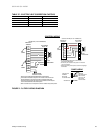
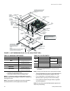
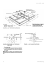
FIGURE 3: UNIT DIMENSIONS DJ180, 210, 240 & 300 (FRONT VIEW)
11-1/2
(A) CONTROL WIRING
ENTRY
COIL
GUARD
KIT
CONDENSER
COILS
All dimensions are in inches. They are
subject to change without notice.
Certified dimensions will be provided
upon request.
(B) POWER
WIRING ENTRY
5
9-3/4
21.00
6-3/8
7-1/8
35
5-7/8
136-1/4
GAS OR
ELECTRIC
HEAT ACCESS
DOT PLUG
(For pressure
drop reading)
BLOWER
COMPARTMENT
ACCESS
(Auxillary)
(C) GAS
SUPPLY
ENTRY
CONTROL BOX
ACCESS
VENT AIR
OUTLET
HOODS
BLOWER MOTOR
ACCESS
BLOWER
ACCESS
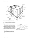
52-5/8
180-19/32
COMPRESSOR ACCESS
(See detail X)
DISCONNECT
SWITCH
LOCATION
ECONOMIZER / MOTORIZED DAMPER
FIXED OUTDOOR INTAKE AIR AND
POWER EXHAUST RAIN HOODS
(See detail Y)
92
46-5/8
35-1/4
33
2-3/4
3-3/4
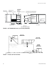
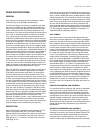
(B) POWER WIRING
ENTRY
BOTTOM SUPPLY
AND RETURN
AIR OPENINGS
(See Note)
(A) CONTROL WIRING
ENTRY
21-1/2
11-1/8
(D)
GAS SUPPLY
ENTRY
UNIT BASE RAILS
Shown separately to illustrate
Bottom Duct openings. Power
and Gas Piping Connection
location.
RETURN
AIR
NOTE:
For curb mounted units, refer to the curb hanger
dimensions of the curb for proper size of the
supply and return air duct connections.
12-1/2
9-1/4
8-1/8
46-5/8
9-3/4
COMBUSTION
AIR INLET HOOD
SUPPLY
AIR
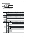
TABLE 38: MINIMUM CLEARANCES
LOCATION
CLEARANCE
Front
36”
Back
24” (Less Economizer)
49” (With Economizer)
Left Side (Filter Access)
24” (Less Economizer)
36” (With Economizer)
Right Side (Cond. Coil)
36”
Below Unit
1
1. Units may be installed on combustible floors made from wood
or class A, B, or C roof covering material.
0”
Above Unit
2
2. Units must be installed outdoors. Overhanging structures or
shrubs should not obstruct condenser air discharge outlet.
72” With 36” Maximum
Horizontal Overhang (For
Condenser Air Discharge)
TABLE 39: UTILITIES ENTRY
HOLE OPENING SIZE (DIA.) USED FOR
A
1-1/8” KO
Control Wiring
Front
3/4” NPS (Fem.) Bottom
B
3-5/8” KO
Power Wiring
Front
3” NPS (Fem.) Bottom
C
2-3/8” KO
Gas Piping (Front)
1
1. One-inch Gas Piping MPT Required.
D
1-11/16” Hole
Gas Piping (Bottom)
1,
2
2. Opening in the bottom to the unit can be located by the side in
the insulation.