


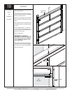

Tools Needed:
EN
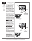
GAGED
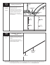
SIDE VIEW
hese
Illustrati
on
,
in co
nj
uncti
on
with th
e
Instruct
io
ns on t
he other
side of
WAR
NING
R
achet B
rac
ke
t
is under
X
TR
E
M
E
S
P
R
I
NG
N
S
IO
N
.
sev
ere o
r
ov
e
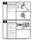
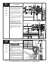
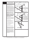
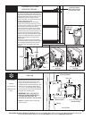
To add spring tension, ensure the ratchet wrench is
set so that it will tighten counter clockwise on the
right hand side, and clockwise on the left hand side.
Place the ratchet wrench with 5/8” socket onto the
winding shaft, pull down to add 3/10 of a turn.
Watch as three teeth of the ratchet wheel pass over
the pawl, creating three “clicks”.
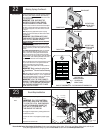
To Remove Spring Tension: To remove spring
tension, ensure the ratchet wrench is set so that it
will tighten counter clockwise on the right hand side
and clockwise on the left hand side. Place the
ratchet wrench with 5/8” socket onto the winding
shaft. Pull down on the ratchet to relieve pressure
between the pawl and the ratchet wheel. Push in on
the pawl to allow the three ratchet wheel teeth to
pass by the pawl, as you carefully allow the ratchet
wrench to be rotated upward by the spring tension.
Release the pawl to allow it to engage with the
ratchet wheel.
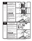
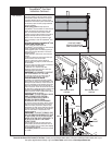
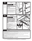
Remove the vice clamps from the vertical tracks,
re-check door balance and adjust if necessary. When
door is balanced and adjusted properly, place the
ratchet pawl knobs in the active position (lower
position).
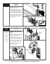
TRACK
VICE CLAMPS
ATTACHED TO
INNER RAIL
OF TRACK
PLACE VICE CLAMPS
ABOVE 3RD ROLLER ON
BOTH VERTICAL TRACK
PAWL KNOB IN LOWER
POSITION
LOWER POSITION
UPPER POSITION
TorqueMaster
®
Plus Reset
Instructions Continued...
PAWL KNOB IN UPPER
POSITION
25
Please Do Not Return This Product To The Store. Contact your local Wayne-Dalton dealer. To find your local Wayne-Dalton dealer, refer to your
local yellow pages/business listings or go to the Find a Dealer section online at www.wayne-dalton.com
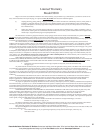
(4) 1/4”-20 X 11/16” SELF
DRILLING SCREWS
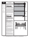
SIDE LOCK
Side Lock
Install the side lock on the second section of the
door. First secure the lock base bracket to the
encap on the lock section, using (2) #8-15 x 1/2”
self drilling screws (2 small pre-drilled holes). Then
secure the lock to the lock base bracket with (4)
1/4” - 20 x 11/16” self tapping screws. Square the
lock assembly with the door section and align with
the square hole in the vertical track.
IMPORTANT: SIDE LOCKS MUST BE
REMOVED OR MADE INOPERATIVE IN
THE UNLOCKED POSITION IF AN
OPERATOR IS INSTALLED ON THE DOOR.
NOTE: After completing this step, continue with
step 9 on page 12.
Power Drill
7/16” Socket Driver
Phillips head screw
driver
LOCK BASE BRACKET
LOCK SECTION
(2) #8 -15 X 1/2” SELF
TAPPING SCREWS
ENDCAP
END
BRACKET
RATCHET
3”
EXTENSION
5/8” SOCKET
MARKS
PAWL