


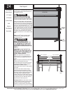
Tools Needed:
21
Please Do Not Return This Product To The Store. Contact your local Wayne-Dalton dealer. To find your local Wayne-Dalton dealer, refer to your
local yellow pages/business listings or go to the Find a Dealer section online at www.wayne-dalton.com
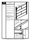
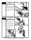
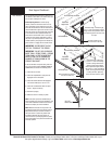
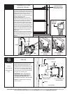
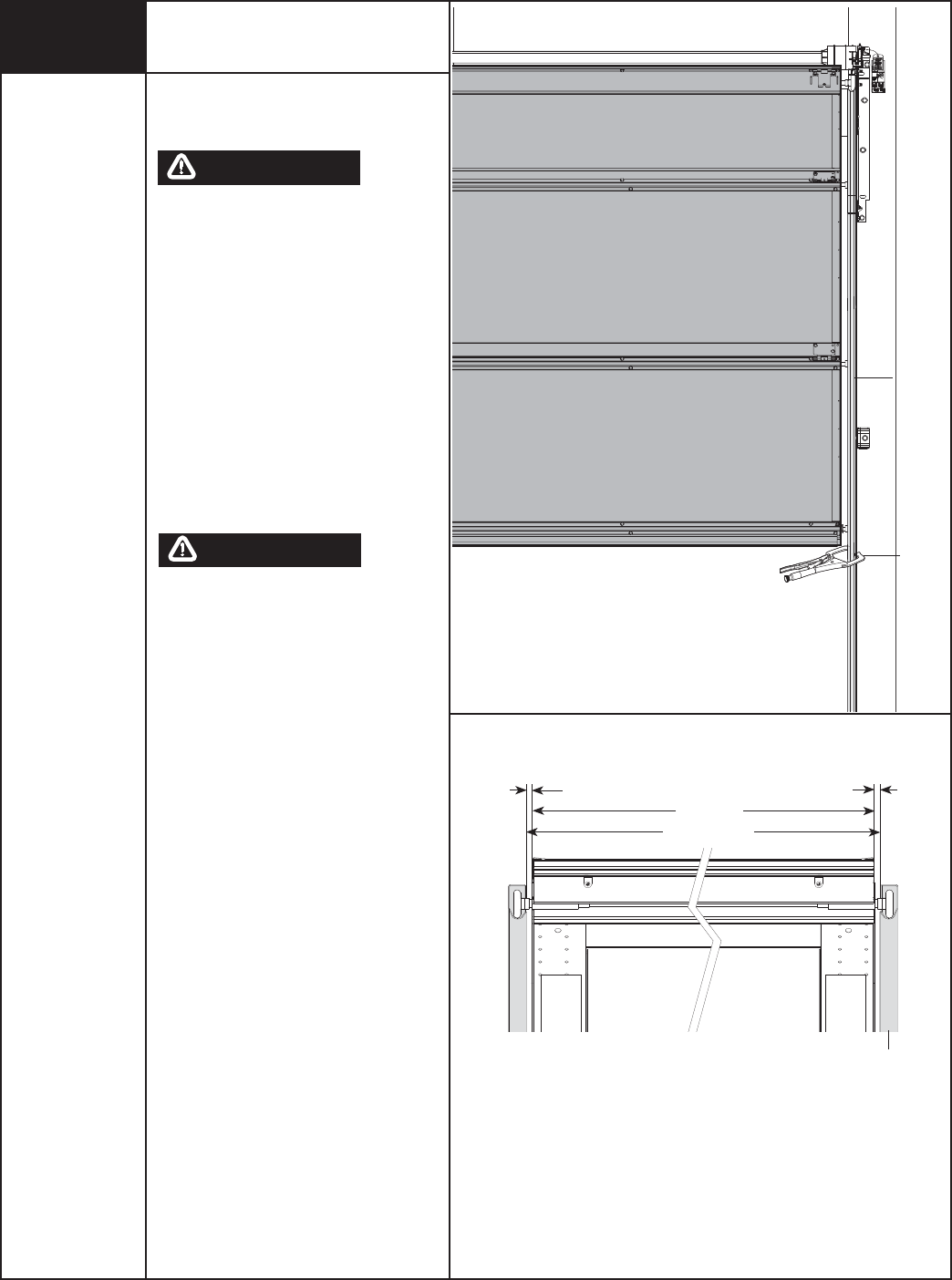
Rear Support
Raise the door until the top section and half of the
next section are in a horizontal position. Do not raise
door any further since the horizontal track are not
yet supported at the rear.
RAISING DOOR FURTHER CAN
RESULT IN DOOR FALLING AND
CAUSE SEVERE INJURY OR DEATH.
Clamp a pair of vice clamps on the vertical tracks
just above the second roller on one side, just below
the second roller on the other side. This will prevent
the door from raising or lowering while installing the
rear support. Using perforated angle, 5/16” x 1-5/8”
hex head lag screws and 5/16” bolts with nuts (may
not be supplied), fabricate rear support for horizontal
tracks. Attach horizontal tracks to the rear supports
with 5/16”-18 x 1-1/4” hex bolts and nuts (may not
be supplied). Horizontal tracks must be level and
parallel to door within 3/4” to 7/8” maximum of door
edge.
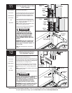
NOTE: If an
i
drive
®
opener is installed, position
horizontal tracks one hole above level when
securting it to the rear.
KEEP HORIZONTAL TRACK
PARALLEL AND WITHIN 3/4” TO
7/8” MAXIMUM OF DOOR EDGE,
OTHERWISE DOOR COULD FALL,
RESULTING IN SEVERE INJURY OR
DEATH.
IMPORTANT: DO NOT SUPPORT THE
WEIGHT OF THE DOOR ON ANY PART OF
THE HORIZONTAL TRACK HANGER THAT
CANTILEVERS 4” OR MORE BEYOND A
SOUND FRAMING MEMBER.
NOTE: If rear supports are to be installed over
drywall, use 5/16” x 2” hex head lag screws, and
make sure lag screws engaged solid structural
lumber.
NOTE: 26” angle must be attached to sound framing
members and nails should not be used.
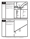
Now, permanently attach the weather seal to both
door jambs and header. (Temporarily attached in
PREPARING THE OPENING on page 6).
Avoid pushing weather seal stop too tightly against
face of door.
Now, lift door and check it’s balance. Adjust, if
door lifts by itself (hard to pull down) or if door is
diffi cult to lift (easy to pull down). Anytime spring
adjustments are made, ratchet pawl knob must be
in the upper position to add/remove required
number of spring turns. To adjust springs, only add
or remove a maximum of 3/10 of a turn (three teeth
of ratchet wheel) at a time. Both sides need to be
adjusted equal on double spring doors.
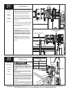
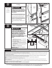
Add Spring Tension: The ratchet wheel is made of
10 teeth. To add spring tension, ensure the ratchet
and socket is set so that it will tighten counter
clockwise on the right hand side, and clockwise on
the left hand side. Place the ratchet with 5/8” socket
24
WARNING
WARNING
Ratchet Wrench
1/2” Socket
1/2” Wrench
(2) Vice Clamps
Level
Hammer
Tape Measure
Step Ladder
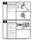
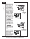
Cable Drum
No space between Ratchet
Pawl and Cable Drum
indicates engagement
Cable Drum
Ratchet Pawl
ENGAGED SIDE VIEW
No space between
Ratchet Pawl and
Cable Drum
ENGAGED UNDERNEATH VIEW
Space between Ratchet Pawl
and Cable Drum
non-indicates engagement
Ratchet Pawl
DISENGAGED SIDE VIEW
No space between
Ratchet Pawl and
DISENGAGED U
NDERNEATH VIEW
UPPER POSITION
LOWER POSITION
UPPER POSITION SIDE VIEW
Ratchet Pawl in Lower Position
Ratchet Pawl in Upper Position
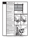
Use these Illustration, in conjunction with the Instructions on the other side of
this label.
W
A
R
N
I
N
G
Ra
c
h
e
t
Br
acke
t
i
s
un
d
e
r
EX
TRE
ME
S
PR
I
NG
TENSIO
N
.
T
o
av
o
i
d
possi
b
le s
e
v
e
r
e or
fa
t
al in
j
u
r
y
,
DO
NO
T
r
e
mo
v
e
f
a
ste
n
ers
f
r
o
m
ra
t
c
h
e
t
b
r
a
c
ke
t
u
n
t
il
spr
ing
(
s)
a
r
e f
ul
ly
w
n
w
o
u
n
d
.
To
sa
f
ely
u
nwin
d
s
p
r
ing
(
s
)
r
e
a
d
a
n
d
f
o
l
l
o
w
t
h
e
dire
c
t
io
ns
i
n
the
in
s
ta
l
l
a
t
ion
in
s
t
r
u
ctio
ns/
own
e
r
s
manua
l
.
DO
N
OT
R
E
M
O
V
E
THI
S
TAG
.
DOOR IN THE
UP POSITION
VERTICAL
TRACK
VICE
CLAMPS
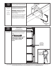
Horizontal tracks
Door edges
3/4” to 7/8” Max
Horizontal
track
3/4” to 7/8” Max