


MX4428 MXP Engineering /Technical Manual Document: LT0273
MXP Technical Description
Page 7-10 24 March 2006 Issue 1.5
In the event that there are isolator bases installed, but there is a short on the section of loop
between the MXP and the first (or last) isolator, the MXP will detect the short and drive the
loop only from the opposite end. Every 30 seconds it will very briefly try reconnecting the
faulty end to see if the fault has gone away. This reconnection must be very brief (if the short
is still present), as it will cause the loop voltage to collapse, and the voltage must be restored
quickly enough so that the addressable devices retain enough charge in their power supply
filter capacitors and do not reset.
7.3 MXP ADJUSTMENTS
None of these adjustments should require changing in the field, unless PCB components
have been changed.
7.3.1 40V ISO SUPPLY VOLTAGE ADJUSTMENT
Disconnect all circuits from the analog loop terminals. Connect 24V to the responder loop
power terminals. Adjust VR1 so that the voltage measured between TP16 “40V ISO” and
TP15 “0V ISO” is 40.0V + / – 0.5V.
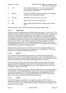
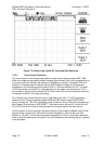
7.3.2 TX DATA VOLTAGE ADJUSTMENT
Disconnect all circuits from the analog loop terminals. Adjust VR2 so that the AC signal
voltage measured with an oscilloscope between TP3 “LINE” and TP15 “0V ISO” is 4.0V -
4.8V p-p.
Refer to
Figure 7.2 for an example waveform. Note that that waveform was captured with an
analog loop and some addressable devices connected and so the measured voltage is
slightly less than that specified.
Note that the MXP will need to be connected to an MX4428 FIP, or standalone mode
activated, for any data to be transmitted.
7.3.3 40V ISO SUPPLY CURRENT LIMIT ADJUSTMENT
Disconnect all circuits from the analog loop terminals. Connect 24V to the responder loop
power terminals. Apply a slowly increasing load current to the loop terminals and check at
what current the overload circuit operates (i.e. current and voltage drop to zero before being
restored by the software - this may happen repeatedly). The overload should occur at a
current of 415mA to 430mA. If it is over this range snip out one of the resistors R22 - R25. If
it is under this range, re-insert one of these resistors (R22 and R23 are 22Ω and R24 and
R25 are 47Ω). Repeat the procedure as required.