MX4428 MXP Engineering /Technical Manual Document: LT0273
MXP Technical Description
Page 7-4 24 March 2006 Issue 1.5
68302 CPU /
Comms Processor
RAM
64kb / 256kb
FLASH
256kb / 512kB
Data / Address
Watchdog /
Reset
Generator
Line Drivers /
Receivers
CHNL1
CHNL2
opto
coupler
opto
coupler
opto
coupler
opto
coupler
opto
coupler
opto
coupler
Connect / Disconnect
24V IN
24V OUT
+VS+V
MIN V
0V
0V IN
0V OUT
0V
0V
Disconn In -
RL3
RL3
Switching PSU
+40V ISO
+5V ISO
0V ISO
Feedback
Latching
Relay
Drive
Isolation Barrier
RESPONDER
LOOP
Pseudo RS232
Interface
Diagnostic
Port
Overcurrent
Detector /
Shutdown
5 bit D/A
Convertor
Modulator
40V ISO
Analog
(NOSEx
)
Loop
Left
Right
0V ISO
0V ISO
Receive
Discriminator
Nosex RX
AD1..5
RL1
RL2
40VReset
Overload -
Relay
Drive
RL1
RL2
Sense
Return Fault
R90
U10
Q17
U11
OC6
Q22
U7C, U7D
OC5
U8
D36
D44
D37
D35
C65.C66
U7A
Q18, Q20
U7B
Q19, Q20
OC1
OC3
OC2
OC4
U6
U1
U3, U4 U2
Q5, Q6
R76-R82
Q14, Q15
Q12, Q2, Q1,
Q4, Q13
Q3, U13A
OC7
MICROPROCESSOR and MEMORY
POWER SUPPLY
ANALOG LOOP INTERFACE
RESPONDER LOOP INTERFACE
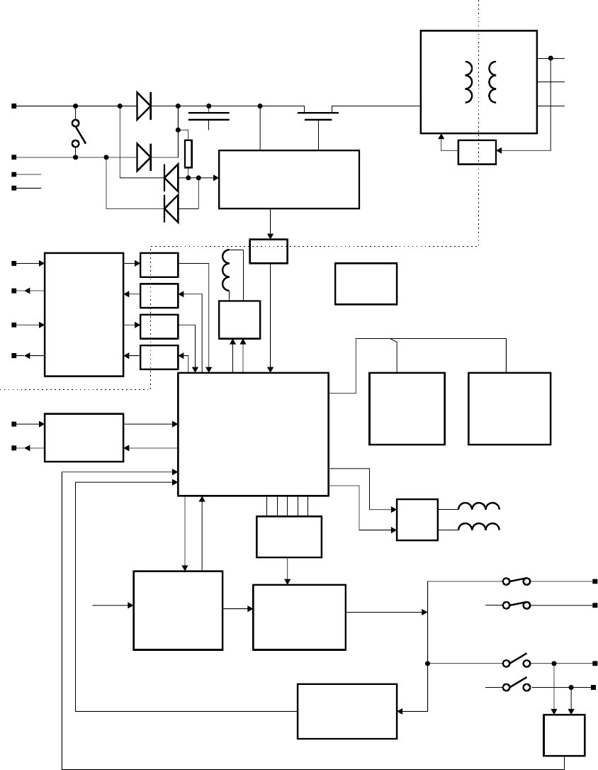
Figure 7.1 MXP Block Diagram
7.2.3 MXP POWER SUPPLY
The raw power to the board is supplied from the 24VIN terminal (via D36) or the 24VOUT
terminal (via D34), or both, depending on the Loop conditions.
This voltage "+V" is smoothed and maintained by reservoir capacitors C65, C66, and C71,
which store sufficient charge to maintain the circuitry under transient loop fault conditions.
From "+V" the following supplies are derived:


