


Document: LT0273 MX4428 MXP Engineering /Technical Manual
MXP Current Consumption
Issue 1.5 24 March 2006 Page 5-3
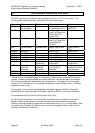
It is of interest to recalculate the current consumption assuming for example the supply
voltage is only 17.0V (the minimum operating voltage of the MXP). In this case the
consumption is increased to 721mA. It can be seen that if the responder loop power wiring
has too much resistance, the voltage to the responders is reduced by their current
consumption, which results in them requiring even more current and compounding the
problem.
5.1.2 QUIESCENT CURRENT
The quiescent current of all responders can be calculated and used to ensure there is
enough battery capacity and supply current at the MX4428.
The quiescent current for the MX loop is calculated as in section
3.2.2, but using the
quiescent current instead of the alarm current. Then the MXP supply current can be
calculated as described in section
5.1. Once again iterative calculations may be required to
adjust for the responder loop voltage drop.
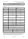
5.1.3 HEAT LOSS
The heat loss from the MXP PCB can be calculated as follows –
W = ITOT(mA) * 40V * ( 1 - PCE) / PCE + IQ(mA) * 24V
Where .....
W = Heat loss in milliwatts
PCE = Power converter efficiency = 0.80
IQ = MXP quiescent current = 50mA at 24V.
ITOT = Total current sourced into the AL and AR terminals, which can
be calculated as shown in Section
3.2.2
Using the above figures, the equation simplifies to
W(mW) = ITOT(mA) * 10V + 1200mW
This can be calculated separately for quiescent and alarm conditions, depending on whether
quiescent or alarm figures are used to calculate IQ.
The maximum possible heat loss is 5.2 watts.