


MX4428 MXP Engineering / Technical Manual Document: LT0273
MXP Loop Filter Board
Page 9-12 24 March 2006 Issue 1.5
9.8 DIM PROCESSING
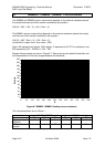
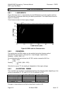
9.8.1 LOAD GRAPH
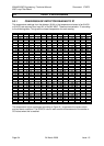
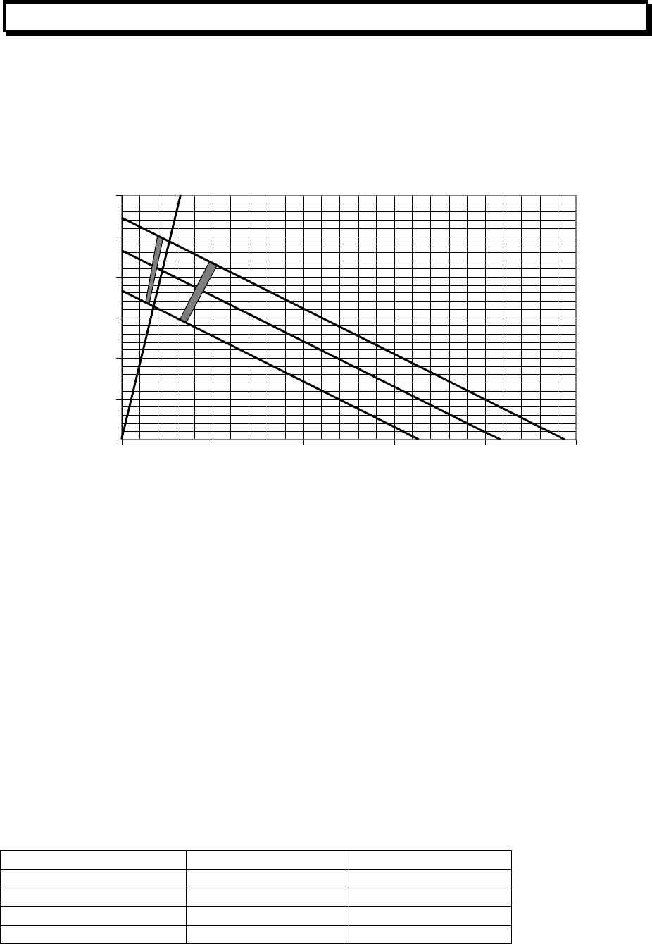
Figure 9.8 shows the V / I characteristics for the DIM detector terminals, together with the
fault and alarm thresholds when using the default parameters. The shaded areas show the
region of uncertainty.
Three lines are shown for three supply voltages.
0
5
10
15
20
25
30
0 102030405
0
Load Current
(
mA
)
Loa
d
V
o
l
tage
28V
24V
19V
4k7 EOL
AL
A
R
M
N
O
R
M
A
L
F
A
U
LT
Figure 9.8 DIM LoadLine Characteristics
9.8.2 DIM MODEL
The reading from the DIM module can be modelled using the following method.
Calculate “R” from a point on the load line = Load Voltage / Load Current.
Reading = 137000 / (560 + R)
For example take the point where the 4k7 EOL resistor crosses the 24V line.
R = 20.8 / .0044
= 4700
Reading = 137000 / (560 + 4700)
= 26
Note that for a given “R”, the reading is independent of the supply voltage.
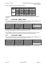
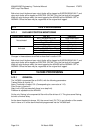
9.8.3 ALGORITHM - DIM800
The unverified input condition is evaluated according to the following table, depending on the
values of parameters P1, P2, and P4. (if P4 is 0, assume it is 225).
Input Condition (Mode 0) Condition (Mode 1)
P4 <= reading <= 255 Alarm Short
P1 <= reading < P4 Alarm Alarm
P2 <= reading < P1 Normal Normal
0 <= reading < P2 Open circuit fault Open circuit fault
Changes in these states are verified as described in section
9.22.