


Document: LT0273 MX4428 MXP Engineering / Technical Manual
Responder Loop Design Considerations
Issue 1.5 24 March 2006 Page 2-5
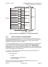
MAPPED
TO
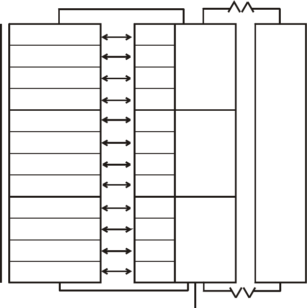
DEVICE 1-16
DEVICE 17-32
DEVICE 33-48
DEVICE 49-64
DEVICE 65-80
DEVICE 81-96
DEVICE 97-112
DEVICE 113-128
DEVICE 129-144
DEVICE 145-160
DEVICE 161-176
DEVICE 177-200
TOTAL OF
200 DEVICES
ANALOG LOOP
ANALOG LOOP
3 LOGICAL RESPONDER MXR
F4000 L
OOP
F4000 LOOP
C1/1 R1/1
C1/2 R1/2
C1/3 R1/3
C1/4 R1/4
C2/1 R2/1
C2/2 R2/2
C2/3 R2/3
C2/4 R2/4
C3/1 R3/1
C3/2 R3/2
C3/3 R3/3
C3/4 R3/4
LOGICAL
RESPONDER
#1
LOGICAL
RESPONDER
#2
LOGICAL
RESPONDER
#3
F4000
MASTER
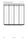
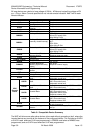
Figure 2.1 Device To Circuit Mapping For 3 Logical Responder MXP
2.2.3 POINT TO CIRCUIT TO ZONE MAPPING
Taking the 3 logical responder example in the previous sections, assume that of the 16
possible device addresses that belong to C1/1, only 10 of these are in fact used, and that 7
are input devices, and the remaining 3 are output devices. Further, assume that the
MX4428 FIP is configured to map C1/1 to ZONE 1.
In this case, an alarm sensed by any of the 7 input devices would put C1/1 into alarm, which
in turn would put ZONE 1 into alarm, a condition indicated on the MX4428 Master front
panel. However, the MXP also generates what is referred to as an extended event,
indicating precisely which of the 7 input devices caused the alarm. This is transmitted to the
MX4428 Master where it is presented on the front panel LCD, entered in the history log and
printed on the logging printer (if programmed).
If, for instance, in this example it was input device 6 that caused the ALARM then the
extended event would take the form .....
"P1/6 ALARM" where .....
..... P = POINT
1 = BASE ADDRESS OF RESPONDER
6 = DEVICE NUMBER
If the Point Text expansion option is fitted at the MX4428 Master, the event will be
associated with a text description of the point.