MX4428 MXP Engineering / Technical Manual Document: LT0273
Analog Loop Design Considerations
Page 4-4 24 March 2006 Issue 1.5
MXP
MX DETECTOR LOOP
AL AR
+VE
+VE
-VE
-VE
L1
L1
L1 L1
L1
M
M
M
M
M
L2
L2
L2
L2
L2
L1
L1
L1
L1
L1
L1
L1
L1
L1
L1
L1
L1
L1
L1
L1
L1
L1
L1
L1
L1
L1
L1
L1
L1
IB
IB
IB
IB IB
L
L
L
L
L
L
L
L
L
L
L
L
L
L
L
L
L
L
L
L
L
L
L
L
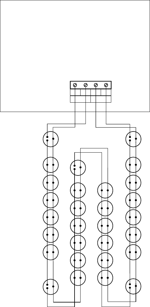
Figure 4.1 Loop with Isolator Bases
Note 1: Although it is not essential to have Isolator Bases between the MXP and the first /
last device on the loop, greater protection is provided by doing so. It is recommended that
the cable between the MXP line terminals and the adjacent Isolator Bases should be kept as
short as possible, and have no devices attached to it. These Isolator Bases could be located
at the MXP without detectors plugged into them.
Note 2: The maximum number of devices between Isolator Bases is 100 or less depending
on the devices. Refer to section
3.2.4.
Note 3: The M and L2 connections are interchangeable.


