


Document: LT0273 MX4428 MXP Engineering / Technical Manual
Device Information and Programming
Issue 1.5 24 March 2006 Page 3-7
3.2 DEVICE HANDLING CAPABILITY
3.2.1 OVERVIEW
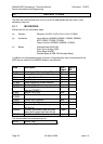
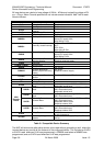
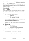
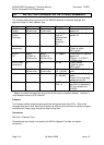
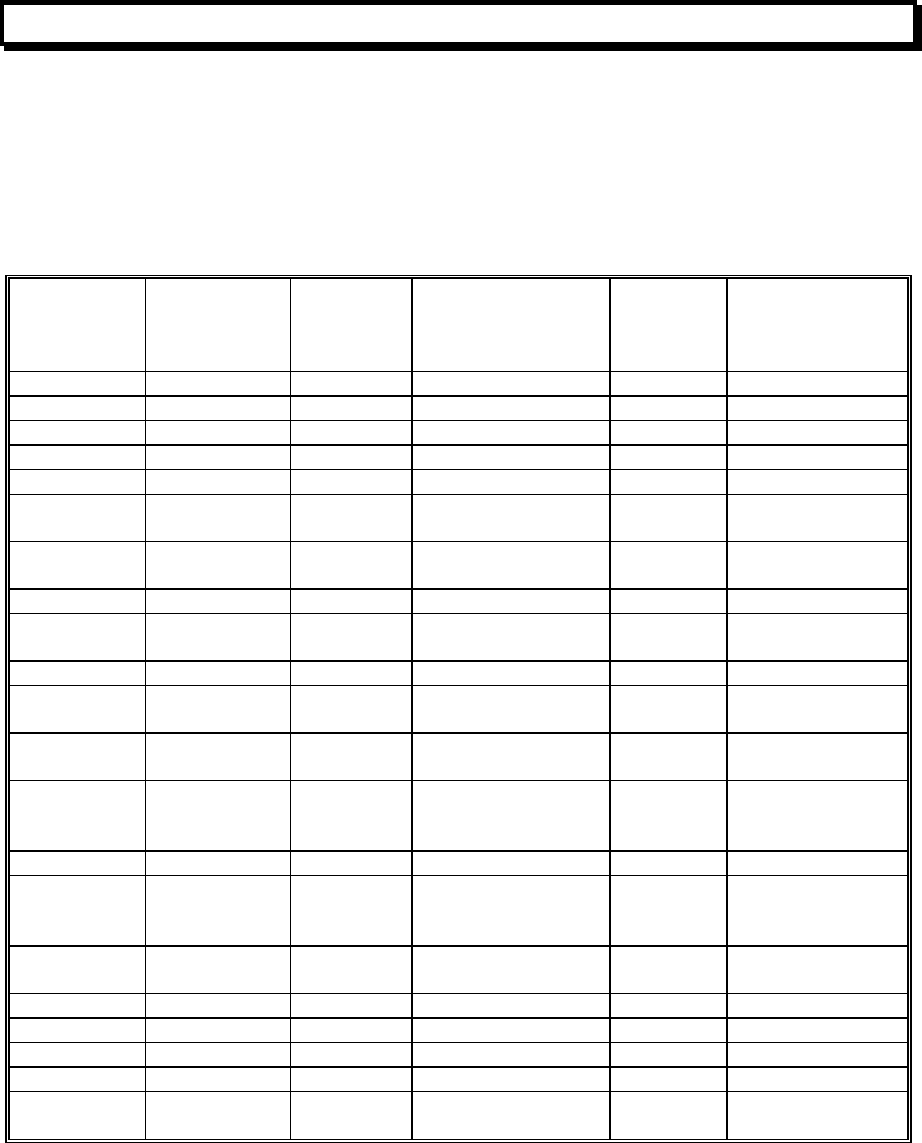
The parameters which determine the maximum number of each device type that can be put
on a loop are as follows. The column “MAX NO. DEVICES” assumes that all devices are of
the same type. If this is not the case, it is necessary to perform the calculations described
below.
DEVICE MAX NO.
DEVICES
Quiescent
Current
Alarm
Current
AC Units
(max 250
total)
IB Units
(max 100 IB
units between
Isolator Bases)
814I 200 330uA 3.0mA 1 1.4
814H 200 250uA 3.0mA 1 1
814PH 200 275uA 3.0mA 1 1.2
814P 200 275uA 3.0mA 1 1.2
814CH 200 275uA 3.0mA 1 1
MIM800 200 275uA 2.8mA (with LED)
275uA (no LED)
1 1.5
MIM801 200 275uA 2.8mA (with LED)
275uA (no LED)
1 1.5
CIM800 200 275uA 2.8mA 1 1
DIM800 200 100uA
(Loop)
100uA (Loop) 1 1
CP820 200 275uA 2.8mA 1 1.5
RIM800 200 285uA 2.8mA (with LED)
285uA (no LED)
1 5
SNM800 200 450uA 3.0mA (with LED)
450uA (no LED)
1 5
LPS800 33 or less,
depends on
load
450uA Load current +
4mA, with
minimum of 12mA
1.5 1
5BI N/A 80uA 0.2 N/A
814SB 40(Quiet)
30(Medium)
24(Loud)
400uA 9mA(Quiet)
12mA(Medium)
15mA(Loud)
2.4 2.5
802SB* 200(Quiet)
50 (Loud)
200uA 1.2mA (Quiet)
6.8mA (Loud)
0.5 2.5
812SB* 18 200uA 21mA 0.5 2.5
901SB* 200 200uA 200uA (Loop) 0.5 2.5
912SB* 200 200uA 200uA( Loop) 0.5 2.5
814RB 200 50uA 100uA 0.3 1.6
VLC800 125 300uA 300uA (no LED)
2.8mA (with LED)
2 1
*Models of MkII Sounder Base
Table 3-2 Device Quantities and Loading
The particular combination of device types, external loads, cable length and type may limit
the total number of devices. This is calculated in the following sections.
There are two types of load which must be considered - DC and AC. Also if isolator bases
are used, the loading between each isolator base must be considered.