


MX4428 MXP Engineering / Technical Manual Document: LT0273
Device Information and Programming
Page 3-40 24 March 2006 Issue 1.5
3.20 DIM800 DETECTOR INPUT MONITOR
3.20.1 GENERAL
The DIM800 Detector Input Module is suitable for interfacing conventional non-addressable
detectors e.g. heat detectors, smoke detectors, beam detectors, etc, onto the MXP loop.
Alarm and o/c fault conditions are determined by the MXP. An alarm can be recognised
within 5 seconds if AVF is not enabled for the circuit, or 15-20 seconds if AVF is enabled.
Recognition of a fault condition takes about 30 seconds.
The DIM800 has two inputs, the state of which are ORed to generate the point status.
Therefore unused inputs must be terminated with the correct EOL.
The DIM800 provides electrical isolation of the detector circuit(s) from the MXP loop.
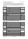
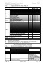
The DIM800 requires an external supply to power the detector circuit and the module itself. If
external power is not provided the DIM800 will not respond to polls and a NODE FAIL fault
will be indicated. The voltage of the external supply at the DIM800 is critical to ensure
compatibility with particular detectors. Refer to
Table 3-4.
The external supply cannot be derived from the MXP loop or the MX4428 responder loop,
and in some cases cannot be taken from the MX4428 main power supply. Where the voltage
range is critical, it is recommended that a dedicated power supply and battery be used. The
voltage drop in the wiring from the power supply to the DIM800 must be calculated to ensure
the supply voltage at the DIM800 is within specification. If multiple DIM800s are on the same
cable, then the maximum current drawn by each DIM800 (e.g. input short circuit) must be
used.
The external supply must comply with AS4428.1 and AS4428.5 and should be set to 27.3V
by default. The wiring from a common PSU to multiple DIM800 modules must be arranged
so that a single open circuit does not prevent alarms from being generated in more than one
zone. A loop arrangement with supervision and a reverse-feed relay can be used to achieve
this - refer to Product Bulletin PBF0200.
If the detector itself requires a 24V power supply that needs to be switched off to reset the
detector, e.g. some beam detectors, refer to Product Bulletin PBF0213 for a suitable
arrangement. Do not use the SW+ and SW- terminals available on early DIM800 models.
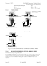
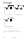
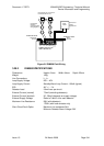
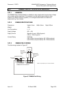
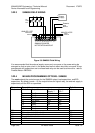
Field wiring of the DIM800 is shown in
Figure 3.6. The wiring instructions for the particular
detector/base must be referred to as some detectors break the negative line, and others the
positive line, when the detector is removed.