


Zone Temperature Sensor (ZTS)
Service Indicator
The ZSM SERVICE LED is a generic
indicator that will signal the closing
of a Normally Open switch at any
time, providing the Indoor Motor
(IDM) is operating. This indicator is
usually used to indicate a clogged
filter, or an air side fan failure.
The RTRM will ignore the closing of
this Normally Open switch for 2 (±1)
minutes. This helps prevent
nuisance SERVICE LED indications.
The exception is the LED will flash
40 seconds after the fan is turned
"On" if the Fan Proving Switch is not
made.
Clogged Filter Switch
This LED will remain lit the entire
time that the Normally Open switch
is closed. The LED will be turned off
immediately after resetting the
switch (to the Normally Open
position), or any time that the IDM
is turned "Off".
If the switch remains closed, and
the IDM is turned "On", the SERVICE
LED will be turned "On" again after
the 2 (±1) minute ignore delay.
This LED being turned "On", will
have no other affect on unit
operation. It is an indicator only.
Fan Failure Switch
When the "Fan Failure" switch is
wired to the RTOM, the LED will
remain flashing the entire time the
fan proving switch is closed,
indicating a fan failure, and it will
shut the unit operations down.
Maintenance
RT-SVX19A-E462
Service Failure
Measure the voltage between
terminals J6-10 & J6-6.
Clogged Filter = Approximately
32 VDC.
Normal = Less than 1 VDC,
approximately 0.75 VDC
Fan Failure = voltage alternates
between 32 VDC & 0.75 VDC.
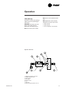
To use LED's for quick status
information at the unit, purchase a
ZSM and connect wires with
alligator clamps to terminals 6
through 10.
Connect each respective terminal
wire (6 through 10) from the Zone
Sensor to the unit J6 terminals 6
through 10.
Note: If the system is equipped
with a programmable zone sensor
THS03, the LED indicators will not
function while the ZSM is
connected.
Resetting Cooling and Ignition
Lockouts
Cooling Failures and Ignition
Lockouts are reset in an identical
manner. Method 1 explains
resetting the system from the space,
Method 2 explains resetting the
system at the unit.
Note: Before resetting Cooling
Failures and Ignition Lockouts,
check the Failure Status Diagnostics
by the methods previously
explained.
Diagnostics will be lost when the
power to the unit is disconnected.
Method 1
To reset the system from the zone,
turn the "Mode" selection switch at
the zone sensor to the "Off"
position.
After approximately 30 seconds,
turn the "Mode" selection switch to
the desired mode, i.e. Heat, Cool or
Auto.
Method 2
To reset the system at the unit,
cycle the unit power by turning the
disconnect switch "Off" and then
"On".
Lockouts can be cleared through the
building management system. Refer
to the building management system
instructions for more information.