


Final installation checklist
• Is the condenser fan and indoor
blower operating correctly, i.e.:
correct rotation and without
undue noise?
• Are the compressors operating
correctly and has the system
charge been checked?
• Has the gas module been
installed as per the procedure in
this manual?
• Have the voltage and running
currents been checked to
determine if they are with in
limits?
• Have the air discharge grilles
been adjusted to balance the
system?
• Has the ductwork been checked
for air leaks and any
condensation?
• Has the heating air temperature
rise been checked?
• Has the indoor airflow been
checked and adjusted if
necessary?
• Has the unit been checked for
tubing and sheet metal rattles
orany unusual noises?
• Are all covers and panels in
placeand properly fastened?
To keep the unit operating safely
and efficiently, the manufacturer
recommends that a qualified service
technician check the entire system
at least once each year, or more
frequently if conditions warrant.
Operation
57RT-SVX19A-E4
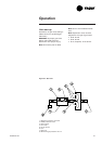
Refer to the ignition control module
diagnostics section for the LED
diagnostic definitions.
When the fan selection switch is set
to the "Auto" position, the RTRM
energizes the supply fan relay (F)
coil approximately 30 second after
initiating the heating cycle to start
the supply fan motor (IDM).
The automatic reset high limit
(TCO1), located in the bottom right
corner of the burner compartment,
protects against abnormally high
leaving air temperatures.
The automatic reset fan fail limit
(TCO2), located in the upper middle
section of the supply fan board,
protects against abnormally high
heat buildup which could occur
because of extended cycling of the
high limit (TCO1) or if the supply
fan motor (IDM) fails to operate.
Should TCO2 open, the RTRM will
energize the supply fan relay (F) in
an attempt to start the fan motor.
The RTRM signals that a heat failure
has occurred by flashing the "Heat"
LED on the zone sensor.
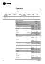
There is a Green LED located in the
Ignition Control Module. The table
below lists the diagnostics and the
status of the LED during the various
operating states.
Table 40 -LED status
Diagnostics Green LED Red LED
1. Powered but no heat dernand Off Off
2. Heat demand without fault Flash ing Off
3. No flame detection on ignition - or signal detected
and then lost
Off Flashing
4. Gas unit incorrectly wired or flame signal detected on
a heat demand
Steady Flashing
5. Internal fault Off Steady