


Installation
13RT-SVX19A-E4
Gas pipework installation
The installation must conform to all
standards and regulations.
The gas supply pipework and gas
stop valve to be installed near the
unit must be sized so as to assure
the gas pressure is sufficient at the
unit inlet when operating at full
load.
CAUTION! Should the pressure at
the unit valve gas inlet be higher
than 0.035 bar, an expansion valve
must be installed.
The pipework must be self-
supporting and the final connection
to the burner must be made by a
flexible pipe. Provide a dust
protection (filter) upstream the unit
connection.
CAUTION!The gas pipework must
not exert any stress on the burner
gas connection.
Note: Expansion valve must be
adapted to the type of gas used:
• G 20 : 20 mb
• G 25 : 25 mb
• G 31 : (Propane): 37 or 50 mb
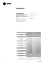
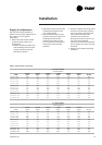
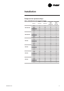
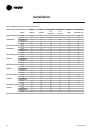
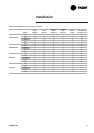
Table 4 - Gas burner models
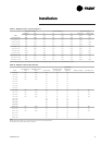
See Table 38 for burner
performance.
Gas leak check procedure
1. Vent the gas line
2. Gas supply line pressure test:
close valve 4 and open valve 2
3. Leak-check the gas pipe
Look for gas pipe leaks using
"Typol", "1000 bulles" or a similar
product. Do not use soapy water.
WARNING! Never use an open
flame to check for gas leaks.
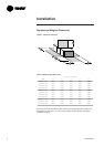
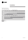
Required gas pressure at the unit
inlet connection are given in
Table 37.
Note:To operate with propane gas,
the burner is fitted with a pressure
limiter (supplied by Trane)
Unit Burner size
YKD/H 155 G350A
YKD/H 175 G350A
YKD/H 200 G350A
YKD/H 250 G350A
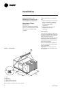
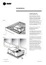
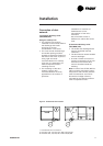
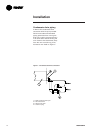
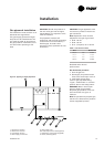
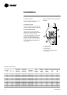
Figure 8 - Typical gas supply Pipework
1 = Evaporator section
2 = Gas burner section
3 = Condenser section
4 = Gas supply connection
5 = Gas supply line
6,8 = Gas stop valve (Field supplied)
7 = Expansion valve (Field supplied)
9 = Filter (Field supplied)