


Maintenance
61RT-SVX19A-E4
Below is the complete listing of
failure indication causes:
System failure
Check the voltage between
terminals 6 and 9 on J6, it should
read approximately 32 VDC. If no
voltage is present, a system failure
has occurred. Refer to Step 4 in the
previous section for the
recommended troubleshooting
procedure.
Heating Failure
Verify Heat Failure by Ignition
Module (IGN) LED indicator:
OFF: No Power or Failure
ON: Normal
Slow Flash: Normal, Heat Call
Fast Flash: Error Code:
1 Flash: Communication Failure
2 Flashes: System Lockout
3 Flashes: Pressure Switch Fail
4 Flashes TC01 or TC02 Open
5 Flashes: Flame w/o Gas Valve
6 Flashes: Flame Rollout Open
Cooling Failure
1. Cooling and heating set point
(slide pot) on the zone sensor
has failed. Refer to the "Zone
Sensor Test Procedure" section.
2. Zone temperature thermistor
ZTEMP on ZTS failed. Refer to
the "Zone Sensor Test Procedure"
section.
3. CC1 or CC2 24 VAC control circuit
has opened, check CC1 & CC2
coils, and any of the controls
below that apply to the unit
(HPC1, HPC2).
4. LPC1 has opened during the
3 minute minimum "on time"
during 4 consecutive compressor
starts, check LPC1 or LPC2 by
testing voltage between the J1-8
& J3-2 terminals on the RTRM
and ground. If 24 VAC is present,
the LPC's has not tripped. If no
voltage is present, LPC's has
tripped.
Service Failure
1. If the supply fan proving switch
has closed, the unit will not
operate (when connected to
RTOM), check the fan motor,
belts, and proving switch.
2. Clogged filter switch has closed,
check the filters.
Simultaneous Heat and Cool Failure
1. Emergency Stop is activated
Method 2
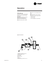
The second method for determining
system status is done by checking
voltage readings at the RTRM (J6).
The system indication descriptions
and the approximate voltages are
listed below.
System Failure
Measure the voltage between
terminals J6-9 & J6-6.
Normal Operation = approximately
32 VDC
System Failure = less than 1 VDC,
approximately 0.75 VDC
Test Mode = voltage alternates
between 32 VDC & 0.75 VDC
Heat Failure
Measure the voltage between
terminals J6-7 & J6-6.
Heat Operating = approximately
32 VDC
Heat Off = less than 1 VDC,
approximately 0.75 VDC
Heating Failure = voltage alternates
between 32 VDC & 0.75 VDC
Cool Failure
Measure the voltage between
terminals J6-8 & J6-6.
Cool Operating = approximately
32 VDC
Cool Off = less than 1 VDC,
approximately 0.75 VDC
Cooling Failure = voltage alternates
between 32 VDC & 0.75 VDC