


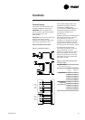

Installation
27RT-SVX19A-E4
Scroll compressors
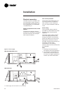
Compressor electrical phasing
Proper phasing of the electrical
power wiring is critical for proper
operation and reliability of the scroll
compressor and fans.
Proper rotation of the scroll
compressor must be established
before the unit is started. This is
accomplished by confirming that
the electrical phase sequence of the
power supply is correct. The motor
is internally connected for clockwise
rotation with the inlet power supply
phased A, B, C.
The direction of rotation may be
reversed by interchanging any two
of the line wires. It is this possible
interchange of wiring that makes a
phase sequence indicator necessary
if the operator is to quickly
determine the phase rotation of the
compressor motor.
The "ABC" indicator on the face of
the phase indicator will glow if
phase is ABC for terminals L1, L2,
L3.
CAUTION! After completion of
wiring, check all electrical
connections, and ensure all
connections are tight. Replace and
secure all electrical box covers and
access doors before leaving unit or
connecting power to circuit
supplying unit.
CAUTION! Units with Scroll
compressors are not equipped with
crankcase heaters.
WARNING !
Disconnect all power,including
remote disconnects, and discharge
all capacitors before servicing.
Follow proper lockout/tagout
procedures to ensure the power
cannot be inadvertently energized.
After power is removed, allow
4 minutes for capacitors to
discharge. Verify with an
appropriate voltmeter that all
capacitors have discharged. Failure
to disconnect power and/or
discharge capacitors before
servicing could result in death or
serious injury. For additional
information regarding the safe
discharge of capacitors, see Trane
Service Bulletin PROD-SVB06A.
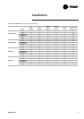
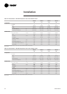
Table 21 - Electrical data - YKD/YKH Unit Wiring
Electrical Characteristics Unit amps
UNIT MPS
Standard Evaporator
Fan Motor
Oversized Evaporator
Fan Motor
Minimum
Circuit
Ampacity
Maximum
Overcurrent
Protective
Device (Fuse
or Circuit
Breaker)
Minimum
circuit
ampacity
Maximum
Overcurrent
Protective
Device (Fuse
or Circuit
Breaker)
Without Electric heat option
TKD/H 155 400/3/50 35 50 36.9 50
TKD/H 175 400/3/50 41 50 41.9 50
TKD/H 200 400/3/50 44 63 44.5 63
TKD/H 250 400/3/50 46.4 63 - -
WKD/H 125 400/3/50 31.9 40 33.8 40
WKD/H 155 400/3/50 35.1 50 37 50
WKD/H 200 400/3/50 50.4 63 50.9 63
YKD/H 155 400/3/50 35.6 50 37.5 50
YKD/H 175 400/3/50 42.3 50 43.2 50
YKD/H 200 400/3/50 44.6 63 45.1 63
YKD/H 250 400/3/50 46.4 63 - -
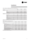
With Electric heat
TKD/H 155 400/3/50 41 63 43 63
TKD/H 175 400/3/50 43 63 43 63
TKD/H 200 400/3/50 61 80 61 80
TKD/H 250 400/3/50 62 80 - -
WKD/H 125 400/3/50 68 80 69.9 80
WKD/H 155 400/3/50 71.2 80 73.1 80
WKD/H 200 400/3/50 104.5 125 105 125