


Operation
49RT-SVX19A-E4
Test procedures
Operating checklist before start-up
• Unit is level, with sufficient
clearance all round
• Duct network is correctly sized
according to the unit
configuration, insulated, and
water-tight
• Condensate drainage line is
correctly sized, equipped with a
trap, and sloped
• Filters are in position, of correct
size and quantity and clean
• Wiring is correctly sized and
connected in accordance with
wiring diagrams
• Power supply lines are protected
by recommended fuses and
correctly earthed
• Thermostat is correctly wired
and positioned
• Unit is checked for refrigerant
charge and leaks
• Indoor and outdoor fans rotate
freely and are fixed on shafts
• Supply fan rotation speed is set
• Access panels and doors are
replaced to prevent air entering
and risks of injury
• Checking of the gas heating
section, in accordance with
above procedure
WARNING! If any operating checks
must be performed with the unit
operating, it is the technician's
responsibility to recognize any
possible hazards and proceed in a
safe manner. Failure to do so could
result in severe personal injury or
death due to electrical shock or
contact with moving parts.
Power-up initialization
CAUTION! Before proceeding with
any test procedure or operation,
make sure that crankcase heaters
have been energized for at least 8
hours.
Units equipped with Scroll
compressors do not have crankcase
heaters.
Note:
Upon power initialization, the RTRM
performs self-diagnostic checks to
insure that all internal controls are
functional. It also checks the
configuration parameters against
the components connected to the
system. The Liteport LED located on
the RTRM module is turned "On"
within 1 second of power-up if
internal operation is okay.
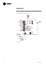
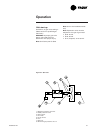
Test mode procedure at the
ReliaTel™ control board
Operating the unit from the roof
using the test mode at the
ReliaTel™ control board.
CAUTION! Before proceeding with
the following test procedures, make
sure that thermostat or zone sensor
is off.
CAUTION! Use one of the following
"Test" procedures to bypass some
time delays and to start the unit at
the control panel.
Each step of unit operation can be
activated individually by
temporarily shorting across the
"Test" terminals for two to three
seconds. The Liteport LED located
on the RTRM module will blink
when the test mode has been
initiated. The unit can be left in any
"Test" step for up to one hour
before it will automatically
terminate, or it can be terminated
by opening the main power
disconnect switch. Once the test
mode has been terminated, the
Liteport LED will glow continuously
and the unit will revert to the
"System" control.