


Controls
31RT-SVX19A-E4
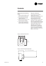
Control wiring
The control circuit is 24 V AC. Unit
includes a 400/24 V transformer.
WARNING!The unit disconnect
switch must be opened and locked
open. Risk of injury and
electrocution.
CAUTION!The unit 24 V transformer
must not be used to power
accessories mounted on site, other
than those proposed by Trane.
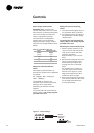
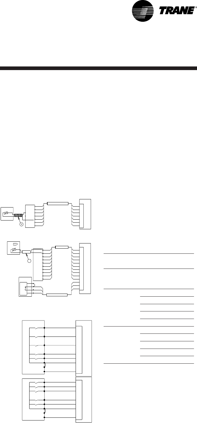
Unit controlled by thermostat
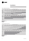
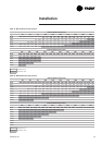
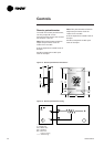
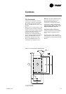
Figure 11 - Thermostat wiring
1
1
2
2
1
3
4
10
9
8
7
6
5
1
1
10
9
8
7
6
5
4
3
2
SR6
THS03
2
1
3
4
10
9
8
7
6
5
11
12
14
1
10
9
8
7
6
5
4
3
2
11
12
14
RTRM
3J6
11
12
14
THA01
10
9
8
7
11
12
14
10
9
8
7
11
12
14
10
9
8
7
11
12
14
10
9
8
7
11
12
14
SR6
THP03
S2
S1
RTRM
3J6
1
2
(WH)
(GN)
(RD)
(BK)
RTRM
3J7
0
W1
G
Y1
Y2
R
0
W1
G
Y1
Y2
R
COM
24V
24V(C)
RTRM
3J7
W1
W2
G
Y1
Y2
R
COM
W1
W2
G
Y1
Y2
R
24V
24V(C)
THS02
4239070
THP02
4240530
THS01
4239060
THP01
4240520
Trane THS01,THS02, THP01 and
THP02 Thermostats are directly
connected to RTRM board
(J7 connector). TRANE THS02 and
THP03 thermostats are directly
connected to RTRM board
(J6 connector).
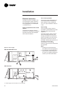
Install the electrical link between the
thermostat (thermostat terminal
strip) and the unit (J6 or J7
connector) in compliance with the
interconnection diagram. The low
voltage wiring must not be laid in
the same pipes as the power cables.
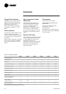
The sizes and lengths of the
thermostat connection wires are
given in Table 29. The total
resistance of these control cables
must not exceed 5 ohms. If the
resistance exceeds this value the
thermostat may not operate with
the same precision.
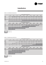
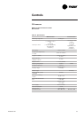
Table 29 - Zone sensor wire size and
maximum length
Maximum length
Zone sensor wire size
Wire
size
(mm²)
Maximum
wire lengh
(m)
THS/THP 03
0.33 45
0.5 76
0.75 115
1. 3 185
2 300
Conventionnal
thermostat
THS/THP 01-02
0.33 10
0.5 15
0.75 23
1. 3 37
2 60