


Controls
RT-SVX19A-E434
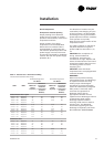
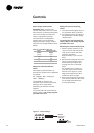
Power supply requirements
CAUTION! Make sure that you
connect the power wire only to the
24V terminal. Connecting the power
wire to the output terminal may
result in equipment damage.
The CO
2
sensor is designed to
operate with a nominal 24 Vac
supply. The power supply should
maintain the voltage between 20 to
26 Vac.
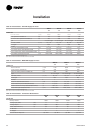
Table 31 - CO
2
sensor wire size
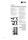
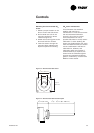
Wiring the wall-mounted CO
2
sensor
DVC setpoint potentiometer on
economizer module can be adjusted
as follows:
0% - 500ppm, 50% - 1000 ppm,
100% - 1500ppm
The outside air damper will
modulate from minimum position
setting to up to 100% while
attempting to maintain the CO
2
setpoint.
To connect the wall mounted CO
2
sensor, Refer to the wiring diagram
provided in the unit.
Cross
section
Maximum wire
Iength
(mm2) (mn)
0.25 50
0.5 100
1 200
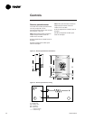
Wiring the duct-mounted CO
2
sensor
1. Connect the DCV signal lwire to
the connector DCV of the ECA
2. Connect the power according to
the guidelines in Power supply
requirements.
To connect the wall mounted CO
2
sensor, Refer to the wiring diagram
provided in the unit.
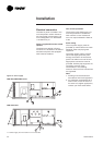
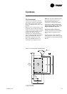
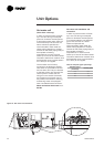
Mounting the wall-mounted sensor
1. Select a proper location in the
room to mount the CO
2
sensor.
Look for an interior wall with
good air circulation,
approximately 1.4 m from the
floor.
2. Remove the back plate from the
sensor and thread the power
wires and output signal wire
through the hole in the back
plate.
For surface wiring, make cut-
outs with pliers to the thinner
section of the upper or lower
edge of the back plate and to
thread the wires through.
3. Mount the back plate to the wall
with screws. Note that the arrow
on the back plate shows the
mounting direction.
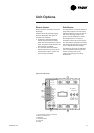
Figure 12 - Jumper settings
OUTPUT
SELECTION
JUMPERS