


STE 58769
– 8 –
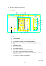
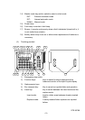
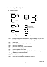
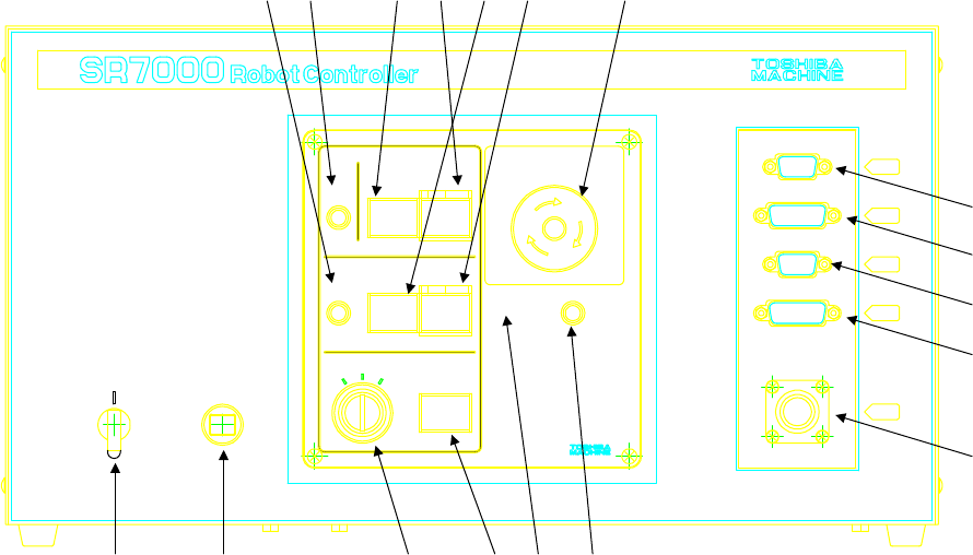
b) Names of the parts of the controller
(1) Controller
ONOFF
STARTSTOP
CYCLE STOP
MANU
INT
EXT
FAULT
POWER
SERVO POWER EMERGENCY
BATTERY
ALARM
J1
J2
PC
FDD
TP
C.P.
DC24V
10AT
POWER
① ②
③
④
⑤
⑥
⑦
⑧⑨⑩⑪
⑫⑭
⑮⑯
⑬
⑰⑱
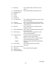
1) Main power switch
2) Circuit protector
3) J1 connector: connector for communication channel 1
4) J2 connector: connector for communication channel 2
5) TP connector: connector for connecting the teaching pendant
6) FDD connector: connector for connecting the floppy disk drive unit
7) Emergency switch
8) Servo power off switch
9) Servo power on switch
10) Stop switch: switch to stop automatic operation
11) Start switch: switch to start automatic operation
12) Cycle stop switch: switch to select the mode of performing 1 cycle of
automatic operation
13) PC connector: connector to connect a PC