


STE 58769
– 19 –
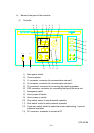
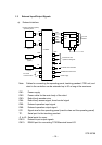
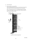
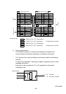
4) Auxiliary input and output signals
DC 24 V wires, including five for input signals from sensors and 4 for control
output signals to electromagnetic valves, are routed to the second arm of the
robot, and allow the opening and closing of the hand and the monitoring of
on/off of sensors.
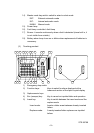
• Output is open collector output and has a capacity of DC24V, 1 A.
• Signal numbers of auxiliary input signals are as given below.
Input: Signal number 220 ··· GRP1 OPN Output: Signal number 214 ··· GRP1
219 ··· GRP1 CLS 213 ··· GRP1
218 ··· GRP2 OPN 212 ··· GRP2
217 ··· GRP2 CLS 211 ··· GRP2
216 ··· WORK
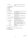
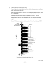
JOES
JOFS
JOFP
JOFS
JOEP
JOES
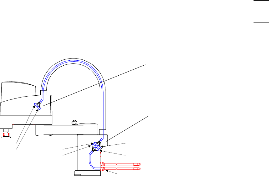
CN4
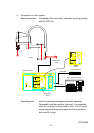
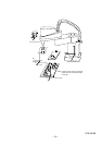
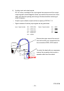
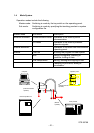
Remove the upper cover of the second
arm and connect your connectors to the
two connectors JOES, JOFS inside it.
To control the hand with your sequencer,
remove the connectors and connect a
separate cable from the outside.