


STE 58769
– 20 –
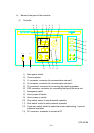
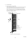
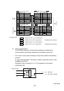
Pin
Signal
Color
name
Color
Pin
Signal
name
Signal
name
Signal
name
Color
Color
Pin
Pin
Color
Color
Sensor
1
2
3
4
5
6
7
GRP1 OPN
GRP1 CLS
GRP2 OPN
GRP2 CLS
WORK
PGND
Shield
Yellow
White (yellow)
Green
White (green)
Red
White (red)
Green
1
2
3
4
5
6
7
GRP1 OPN
GRP1 CLS
GRP2 OPN
GRP2 CLS
WORK
PGND
Shield
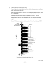
Solenoid valve, etc.
1
2
3
4
5
6
1
2
3
4
5
6
GRP1
GRP1
P24
GRP2
GRP2
P24
Purple
White
Blue
Brown
Yellow
Brown
Yellow
White (yellow)
Green
White (green)
Red
White (red)
Green
Red
Green
Yellow
Brown
Blue
Gray
Green
Purple
White (purple)
Blue
Brown
Yellow
Brown
GRP1
GRP1
P24
GRP2
GRP2
P24
Orange
Purple
Pink
Light green
Light blue
Black/white
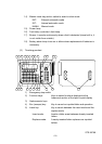
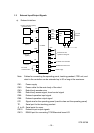
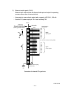
Controller
JOES SM connector 7 poles
JOFS SM connector 7 poles
JOEP SM connector 7 poles JOES
JOFP SM connector 7 poles JOFS
Connector type
JOES
---- SMP–07V–BC (J.S.T Corporation)
JOEP
---- SMR–07V–B (J.S.T Corporation)
Provided by the customer.
JOFS
---- SMR–06V–BC (J.S.T Corporation)
JOFP
---- SMR–06V–B (J.S.T Corporation)
Provided by the customer.
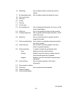
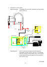
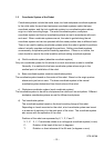
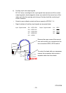
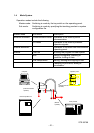
5) Serial communication
The SR7000 controller is furnished with hardware and software for
communication with external equipment as standard components.
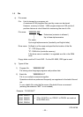
• Port: there are four ports including one exclusively used for the teaching
pendant.
J1 and J2 are switchable. Switching is made by operation mode or robot
language instructions.
Equipment to be connected to J1 to J3 is registered in the system
configuration file.
J2: RS–232C or RS422
J3 J1, J3: RS–232C
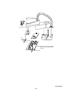
Front Controller Back
J2
J1
Teach pendant