


STE 58769
– 15 –
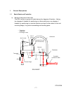
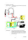
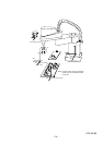
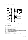
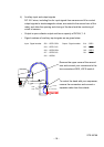
1.3 External Input/Output Signals
a) External interface
Panel is separated (option).
Power supply
TC200/terminal block I/O
For serial communication
External I/O and
operation I/O signals
CN1
CN13
J3
CN12
CN6
CN5
For end
effector
Controller
A
ir
Robot
body
5 m
CN2
CN3
CN4
For serial
communication
Personal
computer
J2
J1
PC
FDD unit
(option)
2 m
FDD
Teach pendant
(option)
7 m
TP
C/P
Operation panel
Note: Cables for connecting the operating panel, teaching pendant, FDD unit, and
robot to the controller can be extended up to 30 m long at the maximum.
CN1: Power supply
CN2: Power cable for the main body of the robot
CN3: Robot body encoder wire
CN4: Robot body sensor signal, hand control signal
CN5: External operation input signal
CN6: External operation output signal
C/P: Signal wire for the operating panel (used to draw out the operating panel)
TP: Serial port for the teaching pendant
J1 to J3: Serial ports for users
CN12: External input output signals
CN13: RS485 port for connecting TC200/terminal board I/O